
Page 239 - Renewable Energy Devices and System with Simulations in MATLAB and ANSYS
P. 239
226 Renewable Energy Devices and Systems with Simulations in MATLAB and ANSYS ®
®
It is also useful to perform emf compensation by adding
* * * = ω * ; ) * * (9.23)
V DC =−ω 1 Li q ; ω 1 r + s ( ω 1 V qc = ω 1 Li sd
sc
and thus allow for lower gain in the dq current controllers.
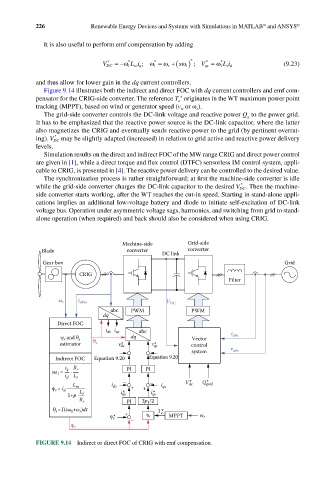
Figure 9.14 illustrates both the indirect and direct FOC with dq current controllers and emf com-
*
pensator for the CRIG-side converter. The reference T originates in the WT maximum power point
e
tracking (MPPT), based on wind or generator speed (v or ω ).
w
r
The grid-side converter controls the DC-link voltage and reactive power Q to the power grid.
g
It has to be emphasized that the reactive power source is the DC-link capacitor, where the latter
also magnetizes the CRIG and eventually sends reactive power to the grid (by pertinent overrat-
*
ing). V DC may be slightly adapted (increased) in relation to grid active and reactive power delivery
levels.
Simulation results on the direct and indirect FOC of the MW range CRIG and direct power control
are given in [1], while a direct torque and flux control (DTFC) sensorless IM control system, appli-
cable to CRIG, is presented in [4]. The reactive power delivery can be controlled to the desired value.
The synchronization process is rather straightforward; at first the machine-side converter is idle
*
while the grid-side converter charges the DC-link capacitor to the desired V DC . Then the machine-
side converter starts working, after the WT reaches the cut-in speed. Starting in stand-alone appli-
cations implies an additional low-voltage battery and diode to initiate self-excitation of DC-link
voltage bus. Operation under asymmetric voltage sags, harmonics, and switching from grid to stand-
alone operation (when required) and back should also be considered when using CRIG.
Machine-side Grid-side
Blade converter DC link converter
Gear box Grid
CRIG
Filter
ω r i abcs V DC
abc PWM PWM
dq
Direct FOC
i ds i qs abc i
ψ r and θ s θ dq Vector abc
estimator s v* ds v* qs control
system v abc
Indirect FOC Equation 9.20 Equation 9.20
i q R r PI PI
sω = i d L r
1
*
L i ds – – i V dc * Q grid
ψ = i d m L + + qs
r
1+p r i* ds i* qs
R r PI 3p 1 /2
θ s =∫(sω +ω )dt T* e
1
r
* + % MPPT ω r
ψ r
–
ψ r
FIGURE 9.14 Indirect or direct FOC of CRIG with emf compensation.