
Page 240 - Renewable Energy Devices and System with Simulations in MATLAB and ANSYS
P. 240
Electric Generators and their Control for Large Wind Turbines 227
9.4 PMSG
9.4.1 Introduction
Three-phase PMSGs with three slots/pole, single-layer winding, and surface PM rotor poles have
been introduced for high power (torque) WTs (e.g., 3 MW, 15 rpm). Other configurations of
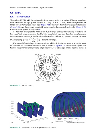
PMSG such as Vernier dual stator type (Figure 9.15), transverse flux type with circular shape coils
(Figure 9.16), and flux reversal types (with tooth-wound coils or multiple pole coils) (Figure 9.17)
have also recently been investigated [8].
All these new configurations, which allow higher torque density, may certainly be suitable for
low-speed/high-torque generators. But, like “flux modulation” machines, they show a smaller power
factor than surface PM rotor distributed winding PMSGs. This simply means a machine converter
XI
kVA overrating: ϕ = tan −1 qrated ; ϕ—power factor angle.
E PM
A brushless DC multiphase reluctance machine, which mimics the operation of an exciter brush
DC machine that brushes off the neutral axis, is shown in Figure 9.18. The current is bipolar and
has two values for the excitation and torque operation. The advantages of this machine include a
Winding Magnet
–A +B
–C
+C
–A
+C +B
–B –B –C +A
+A +A
+A –C –B –B
+B –A +C
–C +C
+B –A
Stator Rotor
FIGURE 9.15 Vernier PMSG.
2600
2500
2400
2300
2200
2100
0
100
200 400 Rotor 1 Rotor 2 Rotor 3 Rotor 4
300 300 Ring coil
400 100 200 Stator lamination—“U” shape profile
(a) 500 –100 0 (b) Stator lamination—“H” shape profile
FIGURE 9.16 Transverse flux axial air-gap PMSM (one phase).