Page 59 - Renewable Energy Devices and System with Simulations in MATLAB and ANSYS
P. 59

46              Renewable Energy Devices and Systems with Simulations in MATLAB  and ANSYS ®
                                                                                ®

                       PV arrays   DC–DC       Central inverter
                                  (optional)
                                                            LV/MV
                                                            trafo.

                                                                      MV/MV
                                                                       trafo.  Grid


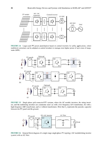
            FIGURE 3.4  Large-scale PV power plant/station based on central inverters for utility applications, where
            multilevel converters can be adopted as central inverters to manage even higher power of up to tens of mega-
            watts (MW).


                                       Optional
                           PV panels
                                      DC              DC                 LF
                       °C
                                           DC             AC
                                 C p
                      (a)
                         PV panels
                                    DC         HF                  DC
                     °C
                                         DC                             AC
                               C p
                    (b)
                                 PV panels  Optional
                                            DC             DC
                             °C
                                                DC              AC
                                      C p
                            (c)
            FIGURE 3.5  Single-phase grid-connected PV systems, where the AC-module inverters, the string invert-
            ers, and the multistring inverters are commonly used: (a) with a low-frequency (LF) transformer, (b) with a
            high-frequency (HF) transformer, and (c) without transformers. Note that C p  represents the parasitic capacitor
            between the PV panel and the ground.


                                         DC–AC inverter     AC filter
                             PV panels
                                    DC link  DC

                                                                             Grid
                        °C         C DC
                                   C p           AC

            FIGURE 3.6  General block diagram of a single-stage single-phase PV topology (AC-module/string inverter
            system) with an AC filter.
   54   55   56   57   58   59   60   61   62   63   64