
Page 62 - Renewable Energy Devices and System with Simulations in MATLAB and ANSYS
P. 62
Overview of Single-Phase Grid-Connected Photovoltaic Systems 49
PV strings/modules Full bridge
LCL filter L 2
i pv
S
S
D
3
1
L
Solar irradiance ambient temperature °C C DC S A S B C f Grid
D 1
3
1
O 2 D 2 4 D 4
C p
Leakage circulating current
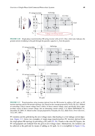
FIGURE 3.10 Single-phase transformerless FB string inverter with an LCL filter, which also indicates the
ground current circulating in the path through the parasitic capacitor C p from the panels.
D Full bridge
PV strings/modules 5
LCL filter
i pv S 5 S 1 D 1 S 3 D L L
A 3 1 2
C DC C f Grid
°C B
S 2 D 2 S 4 D 4
O
C p
(a) DC path
PV strings/modules D 5 Full bridge
i pv S LCL filter
C DC1 5 D S 1 D 1 S 3 D 3 L 1 L 2
7
A
C f Grid
°C B
C DC2 D 8
S 6 S 2 D 2 S 4 D 4
O
C p D 6
(b) DC path
FIGURE 3.11 Transformerless string inverters derived from the FB inverter by adding a DC path: (a) H5
inverter topology and (b) H6 inverter topology. ([a]: Based on the concept proposed by Victor, M. et al., Method
of converting a direct current voltage from a source of direct current voltage, more specifically from a pho-
tovoltaic source of direct current voltage, into an alternating current voltage, U.S. Patent 20050286281 A1,
December 29, 2005; [b]: Based on the concept proposed by Gonzalez, R. et al., IEEE Trans. Power Electron.,
22(2), 693, 2007.)
PV modules and the grid during the zero-voltage states, thus leading to a low leakage current injec-
tion. Figure 3.11 shows two examples of single-stage transformerless PV inverters derived from
the single-phase FB topology by providing a DC path [55, 56]. Thanks to the extra DC bypass, the
PV strings/panels are isolated from the grid at zero-voltage states. Alternatively, the isolation can
be achieved at the grid side by means of adding an AC path. As it is exemplified in Figure 3.12a,