
Page 64 - Renewable Energy Devices and System with Simulations in MATLAB and ANSYS
P. 64
Overview of Single-Phase Grid-Connected Photovoltaic Systems 51
PV strings/modules
i pv S 1 D
C DC1 1
S 3 D 4 LCL filter
A
B
°C L 1 L 2
D 3 S 4
C DC2 S 2 D 2 C f Grid
O
C p
FIGURE 3.13 A transformerless string inverter derived from a neutral point–clamped (NPC) topology—The
Conergy NPC inverter with an LCL filter. (Based on the concept proposed by Knaup, P., Inverter, International
Patent Application, Publication Number: WO 2007/048420 A1, Issued May 3, 2007.)
DC–DC converter DC–AC inverter AC filter
PV panels
DC DC link DC Grid
°C C pv C DC
C p DC AC
FIGURE 3.14 General block diagram of a double-stage single-phase PV topology (with a DC–DC converter).
PV strings/modules Full bridge
i pv L b LCL filter
S 1 D 1 S 3 D 3 L 1 L 2
A
S D C Grid
°C C pv C DC B f
S 2 D 2 S 4 D 4
O
C p
Leakage circulating current
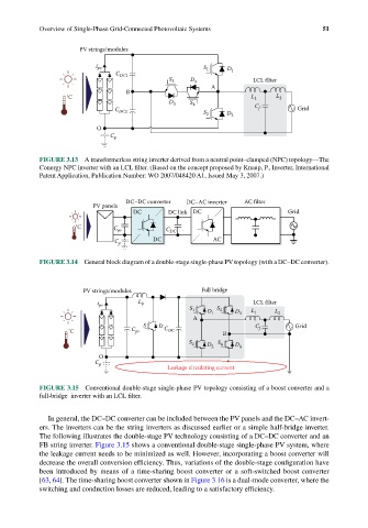
FIGURE 3.15 Conventional double-stage single-phase PV topology consisting of a boost converter and a
full-bridge inverter with an LCL filter.
In general, the DC–DC converter can be included between the PV panels and the DC–AC invert-
ers. The inverters can be the string inverters as discussed earlier or a simple half-bridge inverter.
The following illustrates the double-stage PV technology consisting of a DC–DC converter and an
FB string inverter. Figure 3.15 shows a conventional double-stage single-phase PV system, where
the leakage current needs to be minimized as well. However, incorporating a boost converter will
decrease the overall conversion efficiency. Thus, variations of the double-stage configuration have
been introduced by means of a time-sharing boost converter or a soft-switched boost converter
[63, 64]. The time-sharing boost converter shown in Figure 3.16 is a dual-mode converter, where the
switching and conduction losses are reduced, leading to a satisfactory efficiency.