
Page 65 - Renewable Energy Devices and System with Simulations in MATLAB and ANSYS
P. 65
52 Renewable Energy Devices and Systems with Simulations in MATLAB and ANSYS ®
®
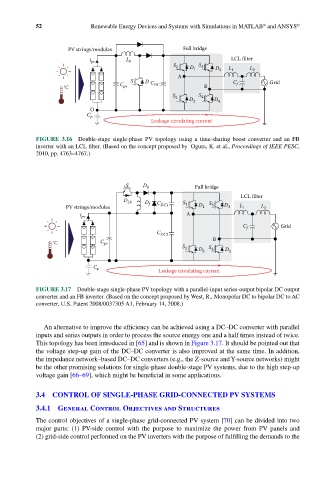
PV strings/modules Full bridge
i pv L b LCL filter
S 1 D 1 S 3 D 3 L 1 L 2
A
S D C C Grid
°C C pv DC B f
S 2 D 2 S 4 D 4
O
C p
Leakage circulating current
FIGURE 3.16 Double-stage single-phase PV topology using a time-sharing boost converter and an FB
inverter with an LCL filter. (Based on the concept proposed by Ogura, K. et al., Proceedings of IEEE PESC,
2010, pp. 4763–4767.)
S D b Full bridge
LCL filter
D Lb D C S S
PV strings/modules f DC1 1 D 1 3 D 3 L 1 L 2
i pv A
C f Grid
C DC2
°C C pv B
S 2 D 2 S 4 D 4
C p Leakage circulating current
FIGURE 3.17 Double-stage single-phase PV topology with a parallel-input series-output bipolar DC output
converter and an FB inverter. (Based on the concept proposed by West, R., Monopolar DC to bipolar DC to AC
converter, U.S. Patent 2008/0037305 A1, February 14, 2008.)
An alternative to improve the efficiency can be achieved using a DC–DC converter with parallel
inputs and series outputs in order to process the source energy one and a half times instead of twice.
This topology has been introduced in [65] and is shown in Figure 3.17. It should be pointed out that
the voltage step-up gain of the DC–DC converter is also improved at the same time. In addition,
the impedance network–based DC–DC converters (e.g., the Z-source and Y-source networks) might
be the other promising solutions for single-phase double-stage PV systems, due to the high step-up
voltage gain [66–69], which might be beneficial in some applications.
3.4 CONTROL OF SINGLE-PHASE GRID-CONNECTED PV SYSTEMS
3.4.1 General Control Objectives and Structures
The control objectives of a single-phase grid-connected PV system [70] can be divided into two
major parts: (1) PV-side control with the purpose to maximize the power from PV panels and
(2) grid-side control performed on the PV inverters with the purpose of fulfilling the demands to the