
Page 70 - Renewable Energy Devices and System with Simulations in MATLAB and ANSYS
P. 70
Overview of Single-Phase Grid-Connected Photovoltaic Systems 57
Grid voltage Locked phase
PD ε PI-LF υ VCO
υ g θ΄
θ–θ΄ k ε+k ∫ε ∫υ
p
i
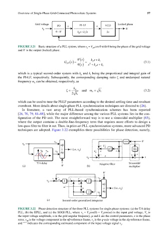
FIGURE 3.21 Basic structure of a PLL system, where v g = V gm cos θ with θ being the phase of the grid voltage
and θ′ is the output (locked) phase.
′ θ s () p +
G pll () = = 2 ks k i (3.1)
s
p +
θ s () s + k sk i
which is a typical second-order system with k and k being the proportional and integral gain of
i
p
the PI-LF, respectively. Subsequently, the corresponding damping ratio ζ and undamped natural
frequency ω can be obtained, respectively, as
n
ζ = k p and ω = k i (3.2)
n
2 k i
which can be used to tune the PI-LF parameters according to the desired settling time and resultant
overshoot. More details about single-phase PLL synchronization techniques are directed to [26].
In literature, a vast array of PLL-based synchronization schemes has been reported
[26, 70, 79, 81–88], while the major difference among the various PLL systems lies in the con-
figuration of the PD unit. The most straightforward way is to use a sinusoidal multiplier [85],
where the output contains a double-line-frequency term that requires more efforts to design a
low-pass filter to filter it out. Thus, in prior-art PLL synchronization systems, more advanced PD
techniques are adopted. Figure 3.22 exemplifies three possibilities for phase detection, namely,
υ α cos θ΄
υ g αβ × V΄ g ×
υ β υ α υ β dq ε (i.e., υ q ) υ΄ g × µ∫ × sin
+ – e × ×
υ g ε
T/4 delay Adaptive filter Sinusoidal
(a) θ΄ (b) multiplier
θ΄
+ – + × υ α
υ g e k ∫
– × αβ
ω΄ × ε (i.e., υ )
q
∫ υ β dq
×
(c) Second-order generalized integrator
FIGURE 3.22 Phase detection structure of the three PLL systems for single-phase systems: (a) the T/4 delay
PLL, (b) the EPLL, and (c) the SOGI-PLL, where v g = V g cos(θ) = V g cos(ωt) is the input grid voltage, V g is
the input voltage amplitude, ω is the grid angular frequency, μ and k are the control parameters, ε is the phase
error, v αβ is the voltage component in the αβ-reference frame, v q is the q-axis voltage in the dq-reference frame,
and “′” indicates the corresponding estimated component of the input voltage signal v g .