
Page 73 - Renewable Energy Devices and System with Simulations in MATLAB and ANSYS
P. 73
60 Renewable Energy Devices and Systems with Simulations in MATLAB and ANSYS ®
®
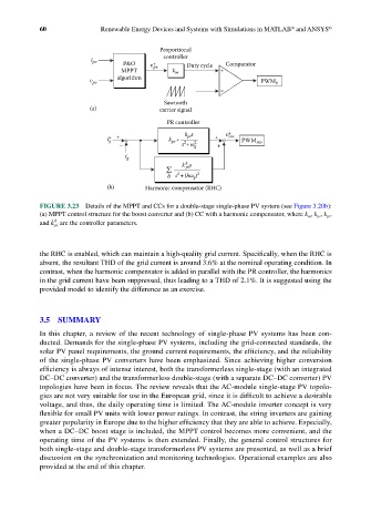
Proportional
controller
i pv P&O υ* Duty cycle Comparator
MPPT pv k m +
υ pv algorithm PWM b
–
Sawtooth
(a) carrier signal
PR controller
i* g + k + k pi s + υ* inv PWM inv
pr
2
– s +ω g 2 +
i g
h
Σ k pi s
2
h s +(hω ) 2
g
(b) Harmonic compensator (RHC)
FIGURE 3.23 Details of the MPPT and CCs for a double-stage single-phase PV system (see Figure 3.20b):
(a) MPPT control structure for the boost converter and (b) CC with a harmonic compensator, where k m , k pr , k pi ,
h
and k pi are the controller parameters.
the RHC is enabled, which can maintain a high-quality grid current. Specifically, when the RHC is
absent, the resultant THD of the grid current is around 3.6% at the nominal operating condition. In
contrast, when the harmonic compensator is added in parallel with the PR controller, the harmonics
in the grid current have been suppressed, thus leading to a THD of 2.1%. It is suggested using the
provided model to identify the difference as an exercise.
3.5 SUMMARY
In this chapter, a review of the recent technology of single-phase PV systems has been con-
ducted. Demands for the single-phase PV systems, including the grid-connected standards, the
solar PV panel requirements, the ground current requirements, the efficiency, and the reliability
of the single-phase PV converters have been emphasized. Since achieving higher conversion
efficiency is always of intense interest, both the transformerless single-stage (with an integrated
DC–DC converter) and the transformerless double-stage (with a separate DC–DC converter) PV
topologies have been in focus. The review reveals that the AC-module single-stage PV topolo-
gies are not very suitable for use in the European grid, since it is difficult to achieve a desirable
voltage, and thus, the daily operating time is limited. The AC-module inverter concept is very
flexible for small PV units with lower power ratings. In contrast, the string inverters are gaining
greater popularity in Europe due to the higher efficiency that they are able to achieve. Especially,
when a DC–DC boost stage is included, the MPPT control becomes more convenient, and the
operating time of the PV systems is then extended. Finally, the general control structures for
both single-stage and double-stage transformerless PV systems are presented, as well as a brief
discussion on the synchronization and monitoring technologies. Operational examples are also
provided at the end of this chapter.