
Page 69 - Renewable Energy Devices and System with Simulations in MATLAB and ANSYS
P. 69
56 Renewable Energy Devices and Systems with Simulations in MATLAB and ANSYS ®
®
Grid
PWM inv
inv
Z g υ*
CC
υ g –
PLL i g i* + g
gm 2 ÷
L 2 ωt θ΄ V 2 ×
+ +
i g
×
υ g × × υ g
C f i g υ g P* ×
L 1 P pv + Q*
–
P
υ inv DC-link controller
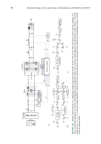
Inverter PWM inv Inverter control υ DC – + General control structure of a single-phase double-stage grid-connected PV inverter with an LCL filter and reactive power injection capability (CC,
υ DC υ* DC (c) PLL): (a) hardware schematics, (b) inverter control diagrams in the dq-reference frame, and (c) inverter control diagrams in the αβ-reference frame, where L t is the total inductance (L t = L 1 + L 2 ), V gm is the grid voltage amplitude, P and Q are the active and reactive power, and subscripts d and q indicate the c
C DC PWM inv
υ DC
inv * υ inv
υ* DC Q* υ*
dq αβ ωt
Boost —ωL t + + + υ d υ q + + + ωL t
L PWM b υ* d υ* d
i pv Boost control P* i q – CC CC i d
MPPT i d + + – i q
υ pv 2/V gm i* + d i* q
i pv –
υ pv Q controller
PV panels P pv DC-link controller + – Q
°C υ DC – + Q*
FIGURE 3.20
(a) DC in the dq-reference frame.
υ* (b)