
Page 68 - Renewable Energy Devices and System with Simulations in MATLAB and ANSYS
P. 68
Overview of Single-Phase Grid-Connected Photovoltaic Systems 55
PWM inv
*
inv υ inv
υ*
dq αβ ωt
Grid Z g + υ q + PWM inv
PLL —ωL t + υ d + + ωL t
υ g υ* d υ* d inv
υ*
L 2 ωt θ΄ i q CC CC i d
CC
i g
–
C f i g υ g i d + + – i q –
L 1 i* d i* q i g +
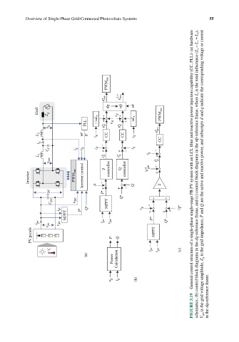
υ inv controller controller gm i* ÷ g General control structure of a single-phase single-stage FB PV system with an LCL filter and reactive power injection capability (CC, PLL): (a) hardware
Inverter PWM inv Inverter control P – P Q V 2 × 2 schematics, (b) control block diagrams in the dq-reference frame, and (c) control block diagrams in the αβ-reference frame, where L t is the total inductance (L t = L 1 + L 2 ), V gm is the grid voltage amplitude, Z g is the grid impedance, P and Q are the active and reactive power, and subscripts d and q ind
υ DC P* + + – Q
C DC υ DC MPPT Q* × + +
i pv P* Q* υ g × × × υ g
MPPT P*
i pv υ pv υ pv i pv υ pv Q*
PV panels P Q MPPT
°C i pv υ pv (c)
(a)
Power Calculation
υ g i g (b)
FIGURE 3.19 in the dq-reference frame.