
Page 63 - Renewable Energy Devices and System with Simulations in MATLAB and ANSYS
P. 63
50 Renewable Energy Devices and Systems with Simulations in MATLAB and ANSYS ®
®
PV strings/modules Full bridge
i pv LCL filter
S 1 D 1 S 3 D 3
A S 5 D 5 L 1 L 2
C DC C f Grid
°C B D 6 S 6
S 2 S
D 2 4 D 4
AC path
O
C p
(a)
PV strings/modules Full bridge
i pv LCL filter
C DC1 S 1 D 1 S 3 D 3 L L
A 1 2
C f Grid
°C B
C DC2 S 2 D 2 S 4 D 4
AC path
O
C p
(b)
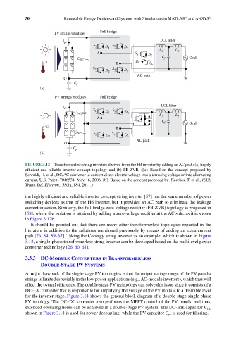
FIGURE 3.12 Transformerless string inverters derived from the FB inverter by adding an AC path: (a) highly
efficient and reliable inverter concept topology and (b) FB-ZVR. ([a]: Based on the concept proposed by
Schmidt, H. et al., DC/AC converter to convert direct electric voltage into alternating voltage or into alternating
current, U.S. Patent 7046534, May 16, 2006; [b]: Based on the concept proposed by Kerekes, T. et al., IEEE
Trans. Ind. Electron., 58(1), 184, 2011.)
the highly efficient and reliable inverter concept string inverter [57] has the same number of power
switching devices as that of the H6 inverter, but it provides an AC path to eliminate the leakage
current injection. Similarly, the full-bridge zero-voltage rectifier (FB-ZVR) topology is proposed in
[58], where the isolation is attained by adding a zero-voltage rectifier at the AC side, as it is shown
in Figure 3.12b.
It should be pointed out that there are many other transformerless topologies reported in the
literature in addition to the solutions mentioned previously by means of adding an extra current
path [26, 54, 59–62]. Taking the Conergy string inverter as an example, which is shown in Figure
3.13, a single-phase transformerless string inverter can be developed based on the multilevel power
converter technology [26, 60, 61].
3.3.3 DC-Module Converters in Transformerless
Double-Stage PV Systems
A major drawback of the single-stage PV topologies is that the output voltage range of the PV panels/
strings is limited especially in the low power applications (e.g., AC-module inverters), which thus will
affect the overall efficiency. The double-stage PV technology can solve this issue since it consists of a
DC–DC converter that is responsible for amplifying the voltage of the PV module to a desirable level
for the inverter stage. Figure 3.14 shows the general block diagram of a double-stage single-phase
PV topology. The DC–DC converter also performs the MPPT control of the PV panels, and thus,
extended operating hours can be achieved in a double-stage PV system. The DC-link capacitor C
DC
shown in Figure 3.14 is used for power decoupling, while the PV capacitor C is used for filtering.
pv