
Page 60 - Renewable Energy Devices and System with Simulations in MATLAB and ANSYS
P. 60
Overview of Single-Phase Grid-Connected Photovoltaic Systems 47
PV module D 5 L 0
LCL filter
i pv D 6 S 5 S 1 D 1 S 3 D 3 L 1 L 2
A
C Grid
C DC D f
°C 7 B
S 2 D 2 S 4 D 4
O
C p
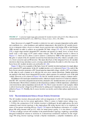
FIGURE 3.7 A universal single-stage grid-connected AC-module inverter with an LCL filter. (Based on the
concept proposed by Prasad, B.S. et al., IEEE Trans. Energy Conver., 23(1), 128, 2008.)
Since the power of a single PV module is relatively low and is strongly dependent on the ambi-
ent conditions (i.e., solar irradiance and ambient temperature), the trend for AC-module invert-
ers is to integrate either a boost or a buck–boost converter into a full-bridge (FB) or half-bridge
(HB) inverter in order to achieve an acceptable DC-link voltage [39–45]. As it is presented in
[39], a single-stage module-integrated PV converter can operate in a buck, boost, or buck–boost
mode with a wide range of PV panel output voltages. This AC-module inverter is shown in
Figure 3.7, where an LCL filter is used to achieve a satisfactory THD of the injected current to
the grid. A variant of the AC-module inverter has been introduced in [40], which is actually a mix
of a boost converter and an FB inverter. The main drawback of the integrated boost AC-module
inverter is that it may introduce a zero-crossing current distortion. In order to solve this issue, the
buck–boost AC-module inverters are preferable [41–44].
Figure 3.8 shows two examples of the buck–boost AC-module inverter topologies for single-phase
grid-connected PV applications. In the AC-module inverter, as it is shown in Figure 3.8a, each of the
buck–boost converters generates a DC-biased unipolar sinusoidal voltage, which is 180° out of phase
to the other in such a manner as to alleviate the zero-cross current distortions. Similar principles
are applied to the buck–boost-integrated FB inverter, which operates for each half-cycle of the grid
voltage. However, as it is shown in Figure 3.8b, this AC-module inverter is using a common source.
In addition to the topologies mentioned earlier, which are mainly based on two relatively indepen-
dent DC–DC converters integrated in an inverter, alternative AC-module inverters are also proposed
in the literature. Most of these solutions are developed in accordance with the impedance–admittance
conversion theory and an impedance network [46–52]. The Z-source inverter is one example, which
is able to boost up the voltage for an FB inverter by adding an LC impedance network, as it is exem-
plified in Figure 3.9. Notably, the Z-source inverter was mostly used in three-phase applications in
the past.
3.3.2 Transformerless Single-Stage String Inverters
The AC-module inverters discussed earlier with an integration of a DC–DC boosting converter
are suitable for use in low power applications. When it comes to higher power ratings (e.g.,
1–5 kWp), the compactness of AC-module inverters is challenged. In such applications, the most
commonly used inverter topology is the single-phase FB string inverter due to its simplicity in
terms of less power switching devices. Figure 3.10 depicts the hardware schematics of a single-
phase FB string inverter with an LCL filter for better power quality. It is also shown in Figure
3.10 that a leakage current will circulate in the transformerless topology, requiring a specifically
designed modulation scheme to minimize it. Conventional modulation methods for the single-
stage FB string inverter topology include a bipolar modulation, a unipolar modulation, and a