
Page 61 - Renewable Energy Devices and System with Simulations in MATLAB and ANSYS
P. 61
48 Renewable Energy Devices and Systems with Simulations in MATLAB and ANSYS ®
®
LCL filter
D 1 L
PV module 1 L 2
i pv
S 1
C DC L b1 C b1 C f Grid
°C
O
C p
L b2
C b2
D 2
(a) S 2
PV module
S D 1 S D 3
i pv 1 3
L b1 D 5 D b2 D 6 LCL filter
L 1 L 2
C
°C DC A
C f Grid
B
S 2 D 2 S 4 D 4
O
C p
(b)
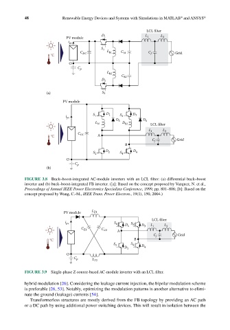
FIGURE 3.8 Buck–boost-integrated AC-module inverters with an LCL filter: (a) differential buck–boost
inverter and (b) buck–boost-integrated FB inverter. ([a]: Based on the concept proposed by Vazquez, N. et al.,
Proceedings of Annual IEEE Power Electronics Specialists Conference, 1999, pp. 801–806; [b]: Based on the
concept proposed by Wang, C.-M., IEEE Trans. Power Electron., 19(1), 150, 2004.)
PV module L Z1
LCL filter
i pv S 1 D S 3 D L L
C Z1 C Z2 A 1 3 1 2
C f Grid
°C B
S 2 S 4
D 2 D 4
O
C p L Z2
FIGURE 3.9 Single-phase Z-source-based AC-module inverter with an LCL filter.
hybrid modulation [26]. Considering the leakage current injection, the bipolar modulation scheme
is preferable [26, 53]. Notably, optimizing the modulation patterns is another alternative to elimi-
nate the ground (leakage) currents [54].
Transformerless structures are mostly derived from the FB topology by providing an AC path
or a DC path by using additional power switching devices. This will result in isolation between the