
Page 99 - Renewable Energy Devices and System with Simulations in MATLAB and ANSYS
P. 99
86 Renewable Energy Devices and Systems with Simulations in MATLAB and ANSYS ®
®
MPP Inverter A
2 × APR
Inverter B
Power
Voltage
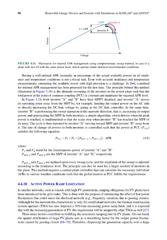
FIGURE 4.16 Illustration for internal APR management using complementary sweep method, in case of a
plant with two CI with the same power level, which operate under identical environmental conditions.
Having a well-defined APR (normally in percentage of the actual available power) in all irradi-
ance and temperature conditions is not a trivial task. Even with accurate irradiance and temperature
measurements, estimating the available power with high precision is a challenge. In [66], a method
for internal APR management has been proposed for the first time. The principle behind this method
(illustrated in Figure 4.16) is the alternate sweeping of the inverters in the power plant such that the
total power at the point of common coupling (PCC) is constant and maintains the required APR level.
In Figure 4.16, both inverter “A” and “B” have their MPPT disabled, and inverter “A” moves
its operating point away from the MPP by, for example, limiting the output power on the AC side
or directly increasing the DC-link voltage by acting as the DC-link controller. At the same time,
inverter “B” is performing the sweep operation in the opposite direction, that is, increasing its output
power, and approaching the MPP. In both inverters, a simple algorithm, which detects when the peak
power is reached, is implemented so that the scans stop when inverter “B” has reached the MPP of
its array. The cycle is then repeated by inverter “A” moving toward MPP and inverter “B” away from
it. The rate of change of powers in both inverters is controlled such that the power at PCC (P PCC )
satisfies the following equation:
P PCC = P A + P B = ( P MPP A + P MPP B) − APR (4.9)
_
_
where
P and P stand for the instantaneous power of inverter “A” and “B”
A
B
P MPP_A and P MPP_B are the MPP of inverter “A” and “B,” respectively
P MPP_A and P MPP_B are updated upon every sweep cycle, and the amplitude of the sweep is adjusted
according to the irradiance level. The principle can also be used for a larger number of inverters in
the plant. This method requires a central plant controller that can calculate the necessary individual
APRs in various weather conditions such that the global reserve at PCC fulfills the requirements.
4.4.10 Active Power Ramp Limitation
In smaller networks, such as islands with high PV penetration, ramping obligations for PV plants have
been introduced in the grid codes. This is done with the purpose of minimizing the effect of fast power
fluctuations that could stress the electrical network (e.g., frequency variation, due to passing clouds).
Although for the moment this characteristic is only for small/island networks, the German transmission
system operator (TSO) has also imposed a 10%/min increasing power ramp limit, and it is expected
that with the increasing penetration of PV, this requirement will be adopted by other TSOs as well [67].
Three main factors contribute to fulfilling the maximum ramping rate by PV plants. On one hand,
the spatial distribution of large PV plants acts as a smoothing factor for the output power fluctua-
tions caused by passing clouds [68–70]. Therefore, dispersing the generation capacity over a large