
Page 94 - Renewable Energy Devices and System with Simulations in MATLAB and ANSYS
P. 94
Three-Phase Photovoltaic Systems: Structures, Topologies, and Control 81
4.4.5 Current Control
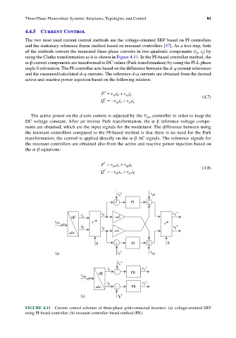
The two most used current control methods are the voltage-oriented SRF based on PI controllers
and the stationary reference frame method based on resonant controllers [47]. As a first step, both
of the methods convert the measured three-phase currents in two quadratic components (i , i ) by
α
β
using the Clarke transformation as it is shown in Figure 4.11. In the PI-based controller method, the
α–β current components are transformed to DC values (Park transformation) by using the PLL phase
angle θ estimation. The PI controller acts based on the difference between the d–q current references
and the measured/calculated d–q currents. The reference d–q currents are obtained from the desired
active and reactive power injection based on the following relation:
*
P = v i d + v i (4.7)
gqq
gd
*
Q =− vi d + vi
gq
gdq
The active power on the d-axis current is adjusted by the V controller in order to keep the
DC
DC voltage constant. After an inverse Park transformation, the α–β reference voltage compo-
nents are obtained, which are the input signals for the modulator. The difference between using
the resonant controllers compared to the PI-based method is that there is no need for the Park
transformation; the control is applied directly on the α–β AC signals. The reference signals for
the resonant controllers are obtained also from the active and reactive power injection based on
the α–β equations:
P = v i + v i (4.8)
*
gββ
gαα
*
Q =− vi + vi
gβα
gαβ
i * v gd
d
– + PI + +
+
i i d v α *
αβ α –ωL
i abc e –jθ e jθ
i β i q v β *
abc ωL
– +
θ + PI + + θ
(a) i * v gq
q
i *
α
i α + v α *
αβ – PR
i abc
i β v β *
abc – + PR
(b) i *
β
FIGURE 4.11 Current control schemes of three-phase grid-connected inverters: (a) voltage-oriented SRF
using PI-based controller; (b) resonant controller–based method (PR).