
Page 90 - Renewable Energy Devices and System with Simulations in MATLAB and ANSYS
P. 90
Three-Phase Photovoltaic Systems: Structures, Topologies, and Control 77
VCO
PD LF
V i V PD V LF ω΄ θ ΄ V΄
x k pd k vco + + 1/s cos
ω i
(a)
V ΄ αβ/dq
α
V α x LF VCO sin
V i – V q V ω + ω΄ θ ΄
QSG + + 1/s
V x ω i cos
β
V ΄
β
SOGI
V i – V e V α
+ k osg + – x 1/s
ω΄
x 1/s
V β
QSG
x –γ 1/s ++ ω i
FLL
(b)
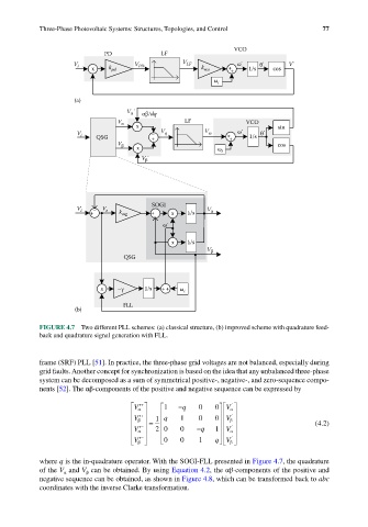
FIGURE 4.7 Two different PLL schemes: (a) classical structure, (b) improved scheme with quadrature feed-
back and quadrature signal generation with FLL.
frame (SRF) PLL [51]. In practice, the three-phase grid voltages are not balanced, especially during
grid faults. Another concept for synchronization is based on the idea that any unbalanced three-phase
system can be decomposed as a sum of symmetrical positive-, negative-, and zero-sequence compo-
nents [52]. The αβ-components of the positive and negative sequence can be expressed by
′ 1 −q 0 ′
+
V α 0 V α
+ ′
′ V β = 1 q 1 0 0 V β (4.2)
′ 2 0 0 −q 1 ′
−
V α − V α ′
′ V β 0 0 1 q V β
where q is the in-quadrature operator. With the SOGI-FLL presented in Figure 4.7, the quadrature
of the V and V can be obtained. By using Equation 4.2, the αβ-components of the positive and
β
α
negative sequence can be obtained, as shown in Figure 4.8, which can be transformed back to abc
coordinates with the inverse Clarke transformation.