
Page 203 - Reservoir Geomechanics
P. 203
185 Compressive and tensile failures in vertical wells
a.
Y
P6
(x 6 , y 6 )
P5
(x 5 , y 5 )
R5
R6
(x 0 , y 0 )
R4 R1
(x 1 , y 1 )
P4
P1 X
(x 4 , y 4 )
R3 R2
P3
(x 3 , y 3 )
(x 2 , y 2 )
P2
P1 = Position of pads
R1 = Corrected length of the arms
b. c.
0 North
270 90
180
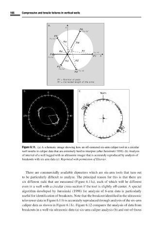
Figure 6.11. (a) A schematic image showing how an off-centered six-arm caliper tool in a circular
well results in caliper data that are extremely hard to interpret (after Jarosinski 1998). (b) Analysis
of interval of a well logged with an ultrasonic imager that is accurately reproduced by analysis of
breakouts with six-arm data (c). Reprinted with permission of Elsevier.
There are commercially available dipmeters which are six-arm tools that turn out
to be particularly difficult to analyze. The principal reason for this is that there are
six different radii that are measured (Figure 6.11a), each of which will be different
even in a well with a circular cross-section if the tool is slightly off-center. A special
algorithm developed by Jarosinski (1998) for analysis of 6-arm data is particularly
useful for identification of breakouts. Note that the breakout identified in the ultrasonic
televiewer data in Figure 6.11bis accurately reproduced through analysis of the six-arm
caliper data as shown in Figure 6.11c. Figure 6.12 compares the analysis of data from
breakouts in a well via ultrasonic data (a) six-arm caliper analysis (b) and out-of-focus