
Page 201 - Reservoir Geomechanics
P. 201
183 Compressive and tensile failures in vertical wells
a. Breakout Azimuth (deg) Calipers (inches) b. Breakout Azimuth (deg) c. IN-GAUGEHOLE
N E S W N 0 5 10 15 N E S W N
11.6 11.6
1
4
Hole 2
11.7 Pad 1 Azimuth 11.7
Azimuth 3
11.8 11.8
BREAKOUT
C2-4
11.9 C1-3 11.9 Depth
Measured Depth (thousand feet) 12.1 Measured Depth (thousand feet) 12.1 WASHOUT
12
12
12.2
12.2
12.3
Hole
12.3
Azimuth
KEYSEAT
12.4 12.4
Pad 1
Azimuth
Well NO BREAKOUTS
12.5 Deviation 12.5
C1-3
12.6 12.6 Cal 1-3
C2-4
4 Cal 2-4
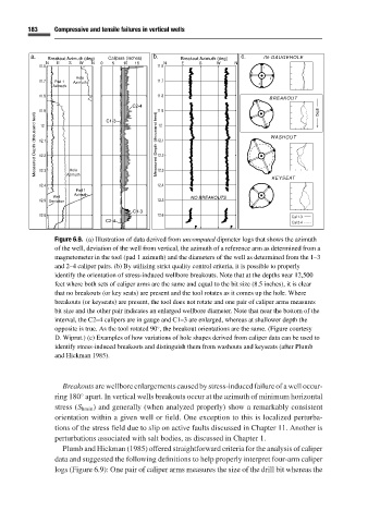
Figure 6.9. (a) Illustration of data derived from uncomputed dipmeter logs that shows the azimuth
of the well, deviation of the well from vertical, the azimuth of a reference arm as determined from a
magnetometer in the tool (pad 1 azimuth) and the diameters of the well as determined from the 1–3
and 2–4 caliper pairs. (b) By utilizing strict quality control criteria, it is possible to properly
identify the orientation of stress-induced wellbore breakouts. Note that at the depths near 12,500
feet where both sets of caliper arms are the same and equal to the bit size (8.5 inches), it is clear
that no breakouts (or key seats) are present and the tool rotates as it comes up the hole. Where
breakouts (or keyseats) are present, the tool does not rotate and one pair of caliper arms measures
bit size and the other pair indicates an enlarged wellbore diameter. Note that near the bottom of the
interval, the C2–4 calipers are in gauge and C1–3 are enlarged, whereas at shallower depth the
opposite is true. As the tool rotated 90 , the breakout orientations are the same. (Figure courtesy
◦
D. Wiprut.) (c) Examples of how variations of hole shapes derived from caliper data can be used to
identify stress-induced breakouts and distinguish them from washouts and keyseats (after Plumb
and Hickman 1985).
Breakouts are wellbore enlargements caused by stress-induced failure of a well occur-
ring 180 apart. In vertical wells breakouts occur at the azimuth of minimum horizontal
◦
stress (S hmin ) and generally (when analyzed properly) show a remarkably consistent
orientation within a given well or field. One exception to this is localized perturba-
tions of the stress field due to slip on active faults discussed in Chapter 11. Another is
perturbations associated with salt bodies, as discussed in Chapter 1.
Plumb and Hickman (1985)offered straightforward criteria for the analysis of caliper
data and suggested the following definitions to help properly interpret four-arm caliper
logs (Figure 6.9): One pair of caliper arms measures the size of the drill bit whereas the