
Page 47 - Reservoir Geomechanics
P. 47
31 Pore pressure at depth in sedimentary basins
a. b. c.
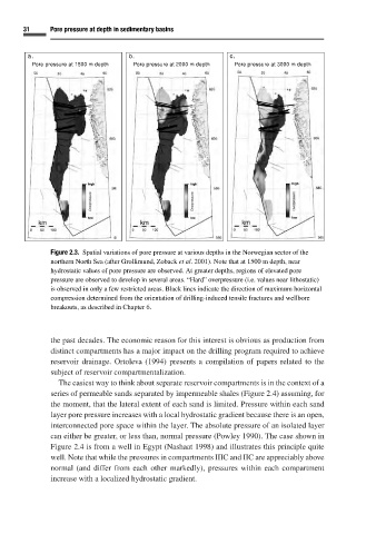
Pore pressure at 1500 m depth Pore pressure at 2000 m depth Pore pressure at 3000 m depth
Figure 2.3. Spatial variations of pore pressure at various depths in the Norwegian sector of the
northern North Sea (after Grollimund, Zoback et al. 2001). Note that at 1500 m depth, near
hydrostatic values of pore pressure are observed. At greater depths, regions of elevated pore
pressure are observed to develop in several areas. “Hard” overpressure (i.e. values near lithostatic)
is observed in only a few restricted areas. Black lines indicate the direction of maximum horizontal
compression determined from the orientation of drilling-induced tensile fractures and wellbore
breakouts, as described in Chapter 6.
the past decades. The economic reason for this interest is obvious as production from
distinct compartments has a major impact on the drilling program required to achieve
reservoir drainage. Ortoleva (1994) presents a compilation of papers related to the
subject of reservoir compartmentalization.
The easiest way to think about separate reservoir compartments is in the context of a
series of permeable sands separated by impermeable shales (Figure 2.4) assuming, for
the moment, that the lateral extent of each sand is limited. Pressure within each sand
layer pore pressure increases with a local hydrostatic gradient because there is an open,
interconnected pore space within the layer. The absolute pressure of an isolated layer
can either be greater, or less than, normal pressure (Powley 1990). The case shown in
Figure 2.4 is from a well in Egypt (Nashaat 1998) and illustrates this principle quite
well. Note that while the pressures in compartments IIIC and IIC are appreciably above
normal (and differ from each other markedly), pressures within each compartment
increase with a localized hydrostatic gradient.