
Page 108 - Robot Builder's Bonanza
P. 108
THE WOODCUTTER’S ART 77
Follow these steps to ensure proper measuring and cutting of your frame.
1. Determine the outside dimension of the frame. For example purposes, we’ll assume
you’re making a 9″ square robot.
2. Let’s start with the top frame piece. Using the miter box, cut a “left- hand” miter at the
tail end of a wood strip. I refer to it as a left- hand miter because the joint will be on the
left side of the frame.
3. With the tape measure placed at the top corner that you just cut, measure exactly 9″.
Using a pencil, make a mark to the immediate right of the 9″ mark on the tape.
4. Again using the miter box, cut a “right- hand” miter, lining up the top of the cut with
the mark. When cutting, be sure the blade is just to the right of the mark. This is called
“keeping the line,” and it ensures the length of the piece will be exactly 9″, even con-
sidering the width of the saw blade (as you will recall from Chapter 6, this is called the
kerf).
5. Now for the bottom frame piece. Pick up the strip that was left over from Step 4. It’ll
already have the proper (right- hand) miter cut. Measure exactly 9″ and mark.
6. Turn the piece over and place in the miter box. Cut a left- hand miter, being sure to
leave the line as you did in Step 4. I’m having you turn the wood strip over so that the
mark at 9″ is along the top. It’s easier to see that way.
7. Now, compare the two frame pieces you’ve cut. If they are slightly different lengths,
carefully sand the longer piece down. When sanding be careful not to round off the cut,
or else the mitered corners won’t meet well.
8. Repeat steps 2 through 7, this time for the left and right pieces. These are also 9″, so
the steps are duplicated exactly.
Assembling the Frame
Once the pieces are cut out, they are then assembled to make a frame. The frame pieces are
held together using L- shaped angle brackets and steel fasteners.
Start by assembling the upper- left corner, using one side piece and one top piece. With a
bracket as a guide, mark a hole for drilling at the corner of one of the frame pieces. Do just
one “leg” of the bracket at a time; don’t try to mark multiple holes. With the wood marked,
move the bracket out of the way and drill the hole (see the next section for details about drill-
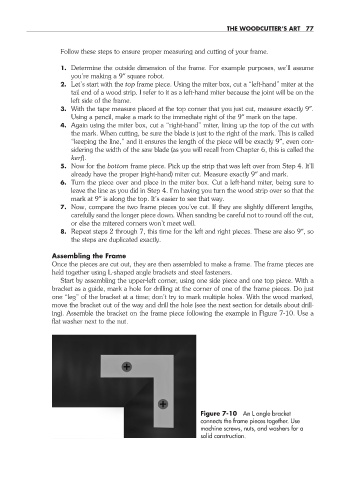
ing). Assemble the bracket on the frame piece following the example in Figure 7-10. Use a
flat washer next to the nut.
Figure 7-10 An L angle bracket
connects the frame pieces together. Use
machine screws, nuts, and washers for a
solid construction.
07-chapter-7.indd 77 4/21/11 11:44 AM