
Page 189 - Robotics Designing the Mechanisms for Automated Machinery
P. 189
5.1 Linear and Angular Displacement Sensors 177
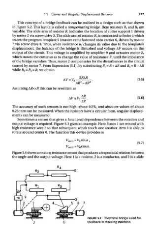
This concept of a bridge feedback can be realized in a design such as that shown
in Figure 5.2. This layout is called a compensating bridge. Here resistors R^ and R 3 are
variable. The slide arm of resistor R l indicates the location of cutter support 1 driven
by motor 2 via screw drive 3. The slide arm of resistor R 3 is connected to feeler 4 which
traces the program template 5 (master cam) fastened onto carrier 6, driven by motor
7 via screw drive 8. Thus, when resistance R 3 changes its value due to the template's
displacement, the balance of the bridge is disturbed and voltage AV" occurs on the
output of the circuit. This voltage is amplified by amplifier 9 and actuates motor 2,
which moves the cutter so as to change the value of resistance R 1 until the imbalance
of the bridge vanishes. Thus, motor 2 compensates for the disturbances in the circuit
caused by motor 7. From Expression (5.1), by substituting J? x = R + AR and R 3 = R-AR
while R 2 = R 4 = R, we obtain
Assuming AR«R this can be rewritten as
The accuracy of such sensors is not high, about 0.5%, and absolute values of about
0.25 mm can be measured. When the resistors have a circular form, angular displace-
ments can be measured.
Sometimes a sensor that gives a functional dependence between the rotation and
output voltage is required. Figure 5.3 gives an example. Here, bases 1 are wound with
high resistance wire 2 so that subsequent winds touch one another. Arm 3 is able to
rotate around center 0. The function this device provides is
Figure 5.4 shows a rotating resistance sensor that produces a trapezoidal relation between
the angle and the output voltage. Here 1 is a resistor, 2 is a conductor, and 3 is a slide
FIGURE 5.2 Electrical bridge used for
feedback in tracking machine.