
Page 191 - Robotics Designing the Mechanisms for Automated Machinery
P. 191
5.1 Linear and Angular Displacement Sensors 179
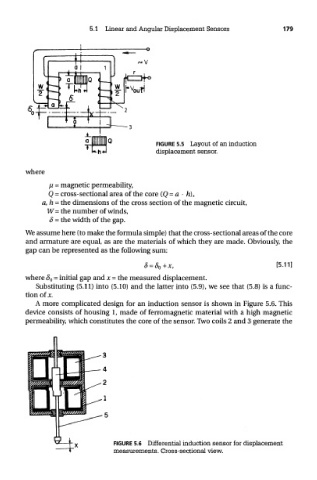
FIGURE 5.5 Layout of an induction
displacement sensor.
where
// = magnetic permeability,
Q = cross-sectional area of the core (Q = a • h),
a,h = the dimensions of the cross section of the magnetic circuit,
W= the number of winds,
8 = the width of the gap.
We assume here (to make the formula simple) that the cross-sectional areas of the core
and armature are equal, as are the materials of which they are made. Obviously, the
gap can be represented as the following sum:
where § 0 = initial gap and x = the measured displacement.
Substituting (5.11) into (5.10) and the latter into (5.9), we see that (5.8) is a func-
tion of jc.
A more complicated design for an induction sensor is shown in Figure 5.6. This
device consists of housing 1, made of ferromagnetic material with a high magnetic
permeability, which constitutes the core of the sensor. Two coils 2 and 3 generate the
FIGURE 5.6 Differential induction sensor for displacement
measurements. Cross-sectional view.