
Page 193 - Robotics Designing the Mechanisms for Automated Machinery
P. 193
5.1 Linear and Angular Displacement Sensors 181
Thus, a circuit without a choke (X L = 0) has an alternating current resistance Z:
where the capacitance Cis calculated from (5.12) for each gap, and co - the frequency
of the alternating current.
The sensitivity of this layout and sensor is high and can be estimated about 10~ 4
mm. However, the measuring range is small.
Specific optical effects can be used as the basis of a very powerful displacement
measurement method. We will briefly describe the principle of a Michelson interfer-
ometer that can be applied for accurate displacement determination in industrial
systems where machine elements must move with high precision. Interference results
from the algebraic addition of the individual components of two or more light beams.
If two of the light beams are of the same frequency, the extent of their interference will
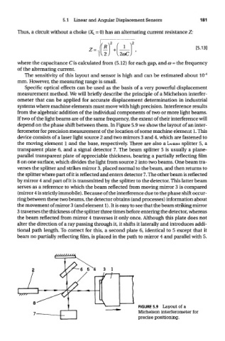
depend on the phase shift between them. In Figure 5.9 we show the layout of an inter-
ferometer for precision measurement of the location of some machine element 1. This
device consists of a laser light source 2 and two mirrors 3 and 4, which are fastened to
the moving element 1 and the base, respectively. There are also a ueain splitter 5, a
transparent plate 6, and a signal detector 7. The beam splitter 5 is usually a plane-
parallel transparent plate of appreciable thickness, bearing a partially reflecting film
8 on one surface, which divides the light from source 2 into two beams. One beam tra-
verses the splitter and strikes mirror 3, placed normal to the beam, and then returns to
the splitter where part of it is reflected and enters detector 7. The other beam is reflected
by mirror 4 and part of it is transmitted by the splitter to the detector. This latter beam
serves as a reference to which the beam reflected from moving mirror 3 is compared
(mirror 4 is strictly immobile). Because of the interference due to the phase shift occur-
ring between these two beams, the detector obtains (and processes) information about
the movement of mirror 3 (and element 1). It is easy to see that the beam striking mirror
3 traverses the thickness of the splitter three times before entering the detector, whereas
the beam reflected from mirror 4 traverses it only once. Although this plate does not
alter the direction of a ray passing through it, it shifts it laterally and introduces addi-
tional path length. To correct for this, a second plate 6, identical to 5 except that it
bears no partially reflecting film, is placed in the path to mirror 4 and parallel with 5.
FIGURE 5.9 Layout of a
Michelson interferometer for
precise positioning.