
Page 192 - Robotics Designing the Mechanisms for Automated Machinery
P. 192
180 Feedback Sensors
magnetic flux. Armature 4 is mounted on rod 5, which serves as a pick-up for the dis-
placement jc. (The rod is made of a nonmagnetic material.) The magnetic flux is divided
into two loops going through the coils and armature 4. The length of the armature's
sections in each loop determines the inductive reactance of each coil. Thus, these coils,
which are a part of a bridge, change its balance (as in the case presented in Figure
5.1b)). Induction sensors are usually limited to measuring ranges not larger than, say,
3 4
15-20 mm. However, the accuracy is on the order of 10 -10 mm.
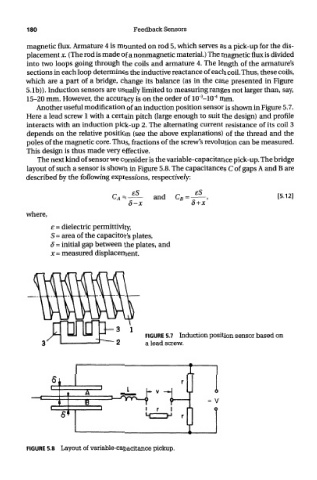
Another useful modification of an induction position sensor is shown in Figure 5.7.
Here a lead screw 1 with a certain pitch (large enough to suit the design) and profile
interacts with an induction pick-up 2. The alternating current resistance of its coil 3
depends on the relative position (see the above explanations) of the thread and the
poles of the magnetic core. Thus, fractions of the screw's revolution can be measured.
This design is thus made very effective.
The next kind of sensor we consider is the variable-capacitance pick-up. The bridge
layout of such a sensor is shown in Figure 5.8. The capacitances C of gaps A and B are
described by the following expressions, respectively:
where,
s = dielectric permittivity,
S = area of the capacitor's plates,
S = initial gap between the plates, and
jc = measured displacement.
FIGURE 5.7 Induction position sensor based on
a lead screw.
FIGURE 5.8 Layout of variable-capacitance pickup.