
Page 190 - Robotics Designing the Mechanisms for Automated Machinery
P. 190
178 Feedback Sensors
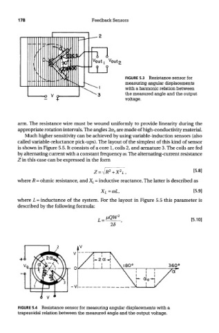
FIGURE 5.3 Resistance sensor for
measuring angular displacements
with a harmonic relation between
the measured angle and the output
voltage.
arm. The resistance wire must be wound uniformly to provide linearity during the
appropriate rotation intervals. The angles 2a 0 are made of high-conductivity material.
Much higher sensitivity can be achieved by using variable-induction sensors (also
called variable-reluctance pick-ups). The layout of the simplest of this kind of sensor
is shown in Figure 5.5. It consists of a core 1, coils 2, and armature 3. The coils are fed
by alternating current with a constant frequency CD. The alternating-current resistance
Z in this case can be expressed in the form
where R = ohmic resistance, and X L = inductive reactance. The latter is described as
where L = inductance of the system. For the layout in Figure 5.5 this parameter is
described by the following formula:
FIGURE 5.4 Resistance sensor for measuring angular displacements with a
trapezoidal relation between the measured angle and the output voltage.