
Page 194 - Robotics Designing the Mechanisms for Automated Machinery
P. 194
182 Feedback Sensors
This plate is called the compensating plate, and it is easy to see that the paths of the
two beams are then identical as regards their passage through refracting plates.
The device described above is named for its inventor, Michelson. Its accuracy is
very high—about 0.0001 mm. The detector obtains information as a sequence of bright
and dark fringes. Thus, the system works in a digital mode, by counting the fringes.
This kind of feedback measuring device, because of its high accuracy, is practically the
only solution for automatic robotic machines in manufacturing integrated circuits.
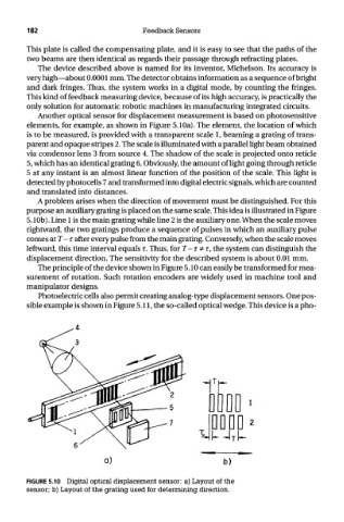
Another optical sensor for displacement measurement is based on photosensitive
elements, for example, as shown in Figure 5.10a). The element, the location of which
is to be measured, is provided with a transparent scale 1, beaming a grating of trans-
parent and opaque stripes 2. The scale is illuminated with a parallel light beam obtained
via condenser lens 3 from source 4. The shadow of the scale is projected onto reticle
5, which has an identical grating 6. Obviously, the amount of light going through reticle
5 at any instant is an almost linear function of the position of the scale. This light is
detected by photocells 7 and transformed into digital electric signals, which are counted
and translated into distances.
A problem arises when the direction of movement must be distinguished. For this
purpose an auxiliary grating is placed on the same scale. This idea is illustrated in Figure
5. lOb). Line 1 is the main grating while line 2 is the auxiliary one. When the scale moves
rightward, the two gratings produce a sequence of pulses in which an auxiliary pulse
comes atT-r after every pulse from the main grating. Conversely, when the scale moves
leftward, this time interval equals r. Thus, for T- T * r, the system can distinguish the
displacement direction. The sensitivity for the described system is about 0.01 mm.
The principle of the device shown in Figure 5.10 can easily be transformed for mea-
surement of rotation. Such rotation encoders are widely used in machine tool and
manipulator designs.
Photoelectric cells also permit creating analog-type displacement sensors. One pos-
sible example is shown in Figure 5.11, the so-called optical wedge. This device is a pho-
FIGURE 5.10 Digital optical displacement sensor: a) Layout of the
sensor; b) Layout of the grating used for determining direction.