Page 211 - Robots Androids and Animatrons : 12 Incredible Projects You Can Build
P. 211

Vcc
                                                       4.7K   –
                                              3.9               6   8  7
                                               K
                                                                5
                                                              +


                                                              –
                                                                2
                                                                     1
                                                                3   4
                                              4.7       3.9   +
                                              K         K


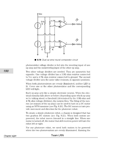
                                          8.19 Dual op-amp neural comparator circuit

                                photoresistor voltage divider is fed into the inverting input of one
                                op-amp and the noninverting input of the other op-amp.
           190                  Two other voltage dividers are needed. They are symmetric but
                                opposite. One voltage divider has a 3.9K-ohm resistor connected
                                to Vcc and a 4.7K-ohm resistor connected to ground. The second
                                voltage divider uses the same value resistors, in opposite positions.

                                When both photoresistors are evenly illuminated, neither LED is
                                lit. Cover one or the other photoresistor and the corresponding
                                LED will light.
                                Each op-amp acts like a simple electronic neuron. When the elec-
                                trical stimulus falls above or below (depending upon which op-amp
                                we’re talking about) a threshold (determined by the 3.9K-ohm and
                                4.7K-ohm voltage dividers), the neuron fires. The firing of the neu-
                                ron (or outputs of the op-amp) can be used to turn on a DC motor
                                using an NPN transistor (see Fig. 8.20). The DC motors in turn pro-
                                vide movement and direction for the photovore robot.

                                To create a simple photovore robot, a chassis is designed that has
                                two  gearbox  DC  motors  (see  Fig.  8.21).  When  both  motors  are
                                powered, the robot moves forward in a straight line. When one
                                motor is turned off, the motor that still receives power will turn the
                                robot left or right.
                                For  our  photovore  robot,  we  need  both  motors  to  be  powered
                                when the two photoresistors are evenly illuminated. Running the
                                                       Team LRN
            Chapter eight
   206   207   208   209   210   211   212   213   214   215   216