Page 213 - Robots Androids and Animatrons : 12 Incredible Projects You Can Build
P. 213

Vcc
                                                                         NPN
                                                4.7K   –                TIP120          Vcc
                                      3.9               6   8  7     1K         M
                                       K
                                                        5
                                                       +

                                                                         NPN            Vcc
                                                                        TIP120
                                                       –
                                                        2            1K         M
                                                             1
                                                        3   4
                                      4.7       3.9    +
                                       K        K
                                                                  Inverter
                                                               4049 or Equiv.

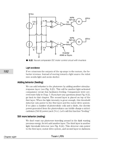
                                  8.22 Neural comparator DC motor control circuit with inverters


                                Light avoidance
           192                  If we crisscross the outputs of the op-amps to the motors, the be-
                                havior reverses. Instead of moving toward a light source the robot
                                now avoids light and seeks shelter.

                        Adding behavior (feeding)

                                We can add behavior to the photovore by adding another stimulus-
                                response layer (see Fig. 8.23). This will be another light-activated
                                comparator circuit that facilitates feeding. Comparators were cov-
                                ered more fully in Chap. 5. If you have any questions about Fig. 8.23,
                                go back to that chapter. The second layer is placed on top of the
                                first layer. When the light intensity is great enough, this threshold
                                detector cuts power to the first layer and the motor drive system.
                                If we place a number of photovoltaic cells and a diode, the electric
                                power generated from the photovoltaics can trickle charge a nickel-
                                cadmium (NiCd) power pack (Vcc). Let’s call this function “feeding.”

                        Still more behavior (resting)

                                We don’t want our photovore traveling around in the dark wasting
                                precious energy. So let’s add another layer. The third layer is another
                                light threshold detector (see Fig. 8.24). This detector cuts power
                                to the first layer, motor drive system, and second layer in darkness


                                                       Team LRN
            Chapter eight
   208   209   210   211   212   213   214   215   216   217   218