
Page 261 - Robots Androids and Animatrons : 12 Incredible Projects You Can Build
P. 261
3
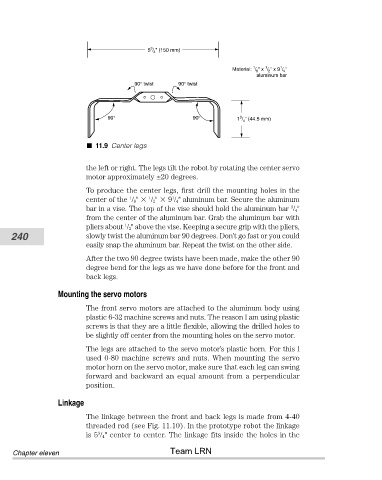
5 / " (150 mm)
4
1
1
1
Material: / " x / " x 9 / "
8 2 4
aluminum bar
90° twist 90° twist
90° 90° 1 / " (44.5 mm)
3
4
11.9 Center legs
the left or right. The legs tilt the robot by rotating the center servo
motor approximately ±20 degrees.
To produce the center legs, first drill the mounting holes in the
1
center of the / 8" / 2" 9 / 4" aluminum bar. Secure the aluminum
1
1
3
bar in a vise. The top of the vise should hold the aluminum bar / 4"
from the center of the aluminum bar. Grab the aluminum bar with
1
pliers about / 2" above the vise. Keeping a secure grip with the pliers,
240 slowly twist the aluminum bar 90 degrees. Don’t go fast or you could
easily snap the aluminum bar. Repeat the twist on the other side.
After the two 90 degree twists have been made, make the other 90
degree bend for the legs as we have done before for the front and
back legs.
Mounting the servo motors
The front servo motors are attached to the aluminum body using
plastic 6-32 machine screws and nuts. The reason I am using plastic
screws is that they are a little flexible, allowing the drilled holes to
be slightly off center from the mounting holes on the servo motor.
The legs are attached to the servo motor’s plastic horn. For this I
used 0-80 machine screws and nuts. When mounting the servo
motor horn on the servo motor, make sure that each leg can swing
forward and backward an equal amount from a perpendicular
position.
Linkage
The linkage between the front and back legs is made from 4-40
threaded rod (see Fig. 11.10). In the prototype robot the linkage
3
is 5 / 4" center to center. The linkage fits inside the holes in the
Team LRN
Chapter eleven