Page 262 - Robots Androids and Animatrons : 12 Incredible Projects You Can Build
P. 262

3
                                                                          5 / "
                                                                            4
                                                threaded rod
                                         Pivot  4-40                    (146 mm)   R        L


                                                      Binding post & screw


                                         4-40
                                        threaded                   Leg
                                         rod
                                                                                Body
                                                                    Plastic
                                                                    washers
                                           Nuts
                                                       Close-Up                                           241

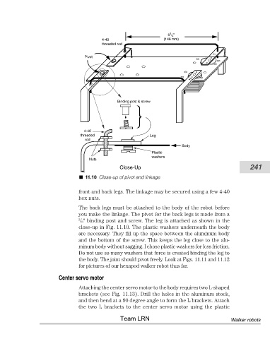
                                         11.10 Close-up of pivot and linkage

                                       front and back legs. The linkage may be secured using a few 4-40
                                       hex nuts.
                                       The back legs must be attached to the body of the robot before
                                       you make the linkage. The pivot for the back legs is made from a
                                       3
                                        / 8" binding post and screw. The leg is attached as shown in the
                                       close-up in Fig. 11.10. The plastic washers underneath the body
                                       are necessary. They fill up the space between the aluminum body
                                       and the bottom of the screw. This keeps the leg close to the alu-
                                       minum body without sagging. I chose plastic washers for less friction.
                                       Do not use so many washers that force is created binding the leg to
                                       the body. The joint should pivot freely. Look at Figs. 11.11 and 11.12
                                       for pictures of our hexapod walker robot thus far.
                               Center servo motor

                                       Attaching the center servo motor to the body requires two L-shaped
                                       brackets (see Fig. 11.13). Drill the holes in the aluminum stock,
                                       and then bend at a 90 degree angle to form the L brackets. Attach
                                       the  two  L  brackets  to  the  center  servo  motor  using  the  plastic
                                                       Team LRN                                    Walker robots
   257   258   259   260   261   262   263   264   265   266   267