
Page 309 - Robots Androids and Animatrons : 12 Incredible Projects You Can Build
P. 309
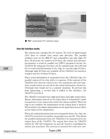
15.7 Assembled PC interface (top)


                        How the interface works

                                The robotic arm contains five DC motors. We need 10 input/output
                                (I/O)  lines  to  control  each  motor  and  direction.  The  parallel
                                (printer) port on the IBM PC and compatibles has only eight I/O
                                lines. To increase the number of I/O lines, the robotic arm interface
                                incorporates a serial in, parallel out (SIPO) integrated circuit, the
                                74LS164. By using just two lines off the parallel port, lines D0 and
           288                  D1, to send serial information to the chip, we can add eight I/O lines.
                                Although eight I/O lines are available off the 74LS164, the interface
                                requires just five of those I/O lines.

                                When serial information is transmitted into the 74LS164 chip, the
                                parallel output of the chip shifts in response. If the outputs of the
                                74LS164 were directly connected to the transistors, the arm func-
                                tions would switch on and off as the serial information clocked in.
                                Obviously that would not be a suitable situation. To prevent this
                                from  happening,  a  second  chip  is  added  to  the  interface,  the
                                74LS373 octal latch.
                                The 74LS373 octal latch has eight input lines and eight output lines.
                                Binary information placed on the input lines is transmitted (made
                                transparent) to the output lines when the chip is enabled. When the
                                chip is not enabled, the information on the output lines is latched.
                                When latched, the binary information on the input lines has no effect
                                on the status of the output lines.
                                When all serial information has been transmitted into the chip, the
                                74LS373 octal latch is enabled, via parallel port pin D2. This allows
                                the parallel information from the 74LS164 to be transmitted to the
                                output lines of the 74LS373. The output lines from the 74LS373
                                switch the TIP 120 transistors on and off, thereby controlling the
                                robotic arm functions. The process is repeated for each new com-
                                                       Team LRN
            Chapter fifteen