
Page 307 - Robots Androids and Animatrons : 12 Incredible Projects You Can Build
P. 307
one transistor (per motor) should be turned on at a time. If two
transistors to the same motor are accidentally turned on at the
same time, it will be the equivalent of creating a short circuit.
Each DC motor in the robotic arm is controlled by two transistors
on the interface in a similar manner.
PC interface construction
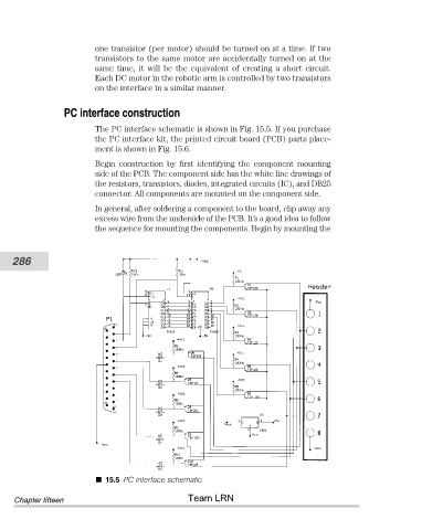
The PC interface schematic is shown in Fig. 15.5. If you purchase
the PC interface kit, the printed circuit board (PCB) parts place-
ment is shown in Fig. 15.6.
Begin construction by first identifying the component mounting
side of the PCB. The component side has the white line drawings of
the resistors, transistors, diodes, integrated circuits (IC), and DB25
connector. All components are mounted on the component side.
In general, after soldering a component to the board, clip away any
excess wire from the underside of the PCB. It’s a good idea to follow
the sequence for mounting the components. Begin by mounting the
286
15.5 PC interface schematic
Team LRN
Chapter fifteen