
Page 308 - Robots Androids and Animatrons : 12 Incredible Projects You Can Build
P. 308
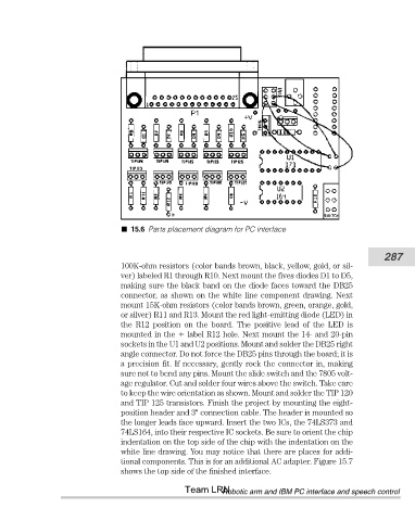
15.6 Parts placement diagram for PC interface


                                                                                                          287
                                       100K-ohm resistors (color bands brown, black, yellow, gold, or sil-
                                       ver) labeled R1 through R10. Next mount the fives diodes D1 to D5,
                                       making sure the black band on the diode faces toward the DB25
                                       connector, as shown on the white line component drawing. Next
                                       mount 15K-ohm resistors (color bands brown, green, orange, gold,
                                       or silver) R11 and R13. Mount the red light-emitting diode (LED) in
                                       the  R12  position  on  the  board.  The  positive  lead  of  the  LED  is
                                       mounted in the   label R12 hole. Next mount the 14- and 20-pin
                                       sockets in the U1 and U2 positions. Mount and solder the DB25 right
                                       angle connector. Do not force the DB25 pins through the board; it is
                                       a precision fit. If necessary, gently rock the connector in, making
                                       sure not to bend any pins. Mount the slide switch and the 7805 volt-
                                       age regulator. Cut and solder four wires above the switch. Take care
                                       to keep the wire orientation as shown. Mount and solder the TIP 120
                                       and TIP 125 transistors. Finish the project by mounting the eight-
                                       position header and 3" connection cable. The header is mounted so
                                       the longer leads face upward. Insert the two ICs, the 74LS373 and
                                       74LS164, into their respective IC sockets. Be sure to orient the chip
                                       indentation on the top side of the chip with the indentation on the
                                       white line drawing. You may notice that there are places for addi-
                                       tional components. This is for an additional AC adapter. Figure 15.7
                                       shows the top side of the finished interface.
                                                       Team LRN
                                                                 Robotic arm and IBM PC interface and speech control