
Page 310 - Robots Androids and Animatrons : 12 Incredible Projects You Can Build
P. 310
mand to the robotic arm. Parallel port lines D3 through D7 control
the TIP 125 transistors directly.
Connecting the interface to the robotic arm
The robotic arm uses a single 6V power supply consisting of four D
cell batteries in the base. The PC interface takes power from the
arm’s 6V power supply. The power supply is used like a bipolar
±3V power supply. Power is tapped from the eight-conductor
Molex connector to the arm base.
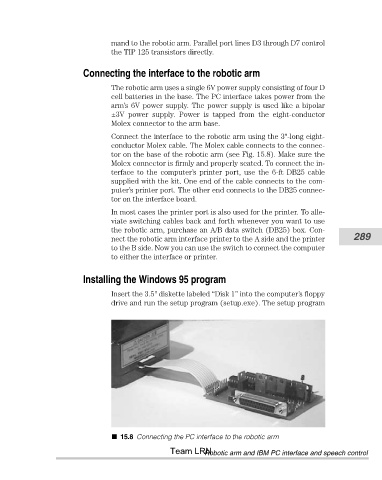
Connect the interface to the robotic arm using the 3"-long eight-
conductor Molex cable. The Molex cable connects to the connec-
tor on the base of the robotic arm (see Fig. 15.8). Make sure the
Molex connector is firmly and properly seated. To connect the in-
terface to the computer’s printer port, use the 6-ft DB25 cable
supplied with the kit. One end of the cable connects to the com-
puter’s printer port. The other end connects to the DB25 connec-
tor on the interface board.
In most cases the printer port is also used for the printer. To alle-
viate switching cables back and forth whenever you want to use
the robotic arm, purchase an A/B data switch (DB25) box. Con-
nect the robotic arm interface printer to the A side and the printer 289
to the B side. Now you can use the switch to connect the computer
to either the interface or printer.
Installing the Windows 95 program
Insert the 3.5" diskette labeled “Disk 1” into the computer’s floppy
drive and run the setup program (setup.exe). The setup program
15.8 Connecting the PC interface to the robotic arm
Team LRN
Robotic arm and IBM PC interface and speech control