
Page 90 - Rock Mechanics For Underground Mining
P. 90
ROCK MASS STRUCTURE AND CHARACTERISATION
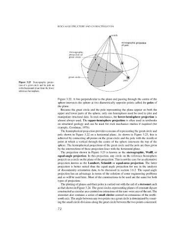
Figure 3.23 Stereographic projec-
tion of a great circle and its pole on
to the horizontal plane from the lower
reference hemisphere.
Figure 3.22. A line perpendicular to the plane and passing through the centre of the
sphere intersects the sphere at two diametrically opposite points called the poles of
the plane.
Because the great circle and the pole representing the plane appear on both the
upper and lower parts of the sphere, only one hemisphere need be used to plot and
manipulate structural data. In rock mechanics, the lower-hemisphere projection is
almost always used. The upper-hemisphere projection is often used in textbooks
on structural geology and can be used for rock mechanics studies if required (for
example, Goodman, 1976).
The hemispherical projection provides a means of representing the great circle and
pole shown in Figure 3.22 on a horizontal plane. As shown in Figure 3.23, this is
achieved by connecting all points on the great circle and the pole with the zenith or
point at which a vertical through the centre of the sphere intersects the top of the
sphere. The hemispherical projections of the great circle and the pole are then given
by the intersections of these projection lines with the horizontal plane.
The projection shown in Figure 3.23 is known as the stereographic, Wulff, or
equal-angle projection. In this projection, any circle on the reference hemisphere
projects as a circle on the plane of the projection. This is not the case for an alternative
projection known as the Lambert, Schmidt or equal-area projection. The latter
projection is better suited than the equal-angle projection for use in the analysis
of discontinuity orientation data, to be discussed in section 3.6.2. The equal-angle
projection has an advantage in terms of the solution of some engineering problems
and so will be used here. Most of the constructions to be used are the same for both
types of projection.
The plotting of planes and their poles is carried out with the aid of a stereonet such
as that shown in Figure 3.24. The great circles representing planes of constant dip are
constructed as circular arcs centred on extensions of the east–west axis of the net. The
stereonet also contains a series of small circles centred on extensions of the north–
south axis. The angle between any two points on a great circle is determined by count-
ing the small circle divisions along the great circle between the two points concerned.
72