
Page 91 - Rock Mechanics For Underground Mining
P. 91
THE HEMISPHERICAL PROJECTION
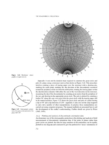
Figure 3.24 Meridional stereo-
graphic or equal area net.
Appendix A sets out the detailed steps required to construct the great circle and
pole of a plane using a stereonet such as that shown in Figure 3.24. This procedure
involves centring a piece of tracing paper over the stereonet with a drawing pin,
marking the north point, marking the dip direction of the discontinuity measured
around the periphery of the net from the north point, rotating the tracing paper so that
the dip direction coincides with either the east or the west direction on the stereonet,
measuring the dip of the discontinuity by counting great circles from the periphery of
the net, and drawing in the appropriate great circle. The pole is plotted by counting a
further 90 along the east–west axis from the great circle with the tracing paper still
◦
in the rotated position. Figure 3.25 shows the great circle and pole of a plane having
a dip of 50 and a dip direction of 230 . Appendix A also sets out the steps required
◦
◦
to carry out a number of other manipulations. In practice these manipulations are
carried out using computer programs. The manual methods are presented here to aid
Figure 3.25 Stereographic projec- the development of the reader’s understanding. Further details are given by Priest
tion of the great circle and pole of the (1985, 1993).
◦
plane 230 /50 .
◦
3.6.2 Plotting and analysis of discontinuity orientation data
An elementary use of the stereographic projection is the plotting and analysis of field
measurements of discontinuity orientation data. If the poles of planes rather than
great circles are plotted, the data for large numbers of discontinuities can be rapidly
plotted on one diagram and contoured to give the preferred or ‘mean’ orientations of
73