Page 116 - Schaum's Outline of Theory and Problems of Electric Circuits
P. 116

WAVEFORMS AND SIGNALS
               CHAP. 6]


                                                         Fig. 6-3                                    105


                                                         Fig. 6-4


                                                         Fig. 6-5


                          6
                                    6
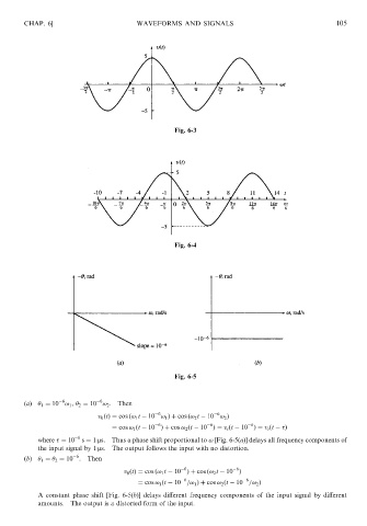
               (a)   1 ¼ 10 ! 1 ,   2 ¼ 10 ! 2 . Then
                                                    6               6
                                    v 0 ðtÞ¼ cos ð! 1 t   10 ! 1 Þþ cos ð! 2 t   10 ! 2 Þ
                                                    6             6           6
                                       ¼ cos ! 1 ðt   10 Þþ cos ! 2 ðt   10 Þ¼ v i ðt   10 Þ¼ v i ðt    Þ
                   where   ¼ 10  6  s ¼ 1 ms.  Thus a phase shift proportional to ! [Fig. 6-5(a)] delays all frequency components of
                   the input signal by 1 ms.  The output follows the input with no distortion.
                              6
               (b)   1 ¼   2 ¼ 10 .  Then
                                                           6              6
                                           v 0 ðtÞ¼ cos ð! 1 t   10 Þþ cos ð! 2 t   10 Þ
                                                           6                6
                                               ¼ cos ! 1 ðt   10 =! 1 Þþ cos ! 2 ðt   10 =! 2 Þ
                   A constant phase shift [Fig. 6-5(b)] delays different frequency components of the input signal by different
                   amounts.  The output is a distorted form of the input.
   111   112   113   114   115   116   117   118   119   120   121