Page 120 - Schaum's Outline of Theory and Problems of Electric Circuits
P. 120

WAVEFORMS AND SIGNALS
               CHAP. 6]
                                                                                                     109
                                                     0       for t < 0
               (d)                           v 4 ðtÞ¼                                               (24)
                                                     sin !t  for t > 0

                                                    0             for t < 0
               (e)                           v 5 ðtÞ¼   t=                                          (25)
                                                    e    cos !t   for t > 0
                                                     t=
               ( f )                         v 6 ðtÞ¼ e    for all t                                (26)
               (g)                           v 7 ðtÞ¼ e  ajtj  for all t                            (27)
               (h)                           v 8 ðtÞ¼ e  ajtj  cos !t  for all t                    (28)
                   Several of these functions are used as mathematical models and building blocks for actual signals in
               analysis and design of circuits.  Examples are discussed in the following sections.


               6.8  THE UNIT STEP FUNCTION
                   The dimensionless unit step function, is defined by

                                                         0    for t < 0
                                                  uðtÞ¼                                             ð29Þ
                                                         1    for t > 0
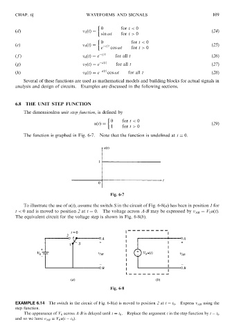
                   The function is graphed in Fig. 6-7.  Note that the function is undefined at t ¼ 0.


                                                         Fig. 6-7
                   To illustrate the use of uðtÞ, assume the switch S in the circuit of Fig. 6-8(a) has been in position 1 for
               t < 0 and is moved to position 2 at t ¼ 0.  The voltage across A-B may be expressed by v AB ¼ V 0 uðtÞ.
               The equivalent circuit for the voltage step is shown in Fig. 6-8(b).


                                                         Fig. 6-8


               EXAMPLE 6.14   The switch in the circuit of Fig. 6-8(a) is moved to position 2 at t ¼ t 0 .  Express v AB using the
               step function.
                   The appearance of V 0 across A-B is delayed until t ¼ t 0 .  Replace the argument t in the step function by t   t 0
               and so we have v AB ¼ V 0 uðt   t 0 Þ:
   115   116   117   118   119   120   121   122   123   124   125