
Page 181 - Schaum's Outline of Theory and Problems of Electric Circuits
P. 181
HIGHER-ORDER CIRCUITS AND COMPLEX FREQUENCY
[CHAP. 8
170
EXAMPLE 8.6 A series RL circuit, with R ¼ 10
and L ¼ 2 H, has an applied voltage v ¼ 10 e 2t cos ð10t þ 308Þ.
Obtain the current i by an s-domain analysis.
di di
st
v ¼ 10 308 e ¼ Ri þ L ¼ 10i þ 2
dt dt
st
Since i ¼ Ie ,
10 308
st
st
10 308 e ¼ 10Ie þ 2sIe st or I ¼
10 þ 2s
Substituting s ¼ 2 þ j10,
10 308 10 308
I ¼ ¼ ¼ 0:48 43:38
10 þ 2ð 2 þ j10Þ 6 þ j20
st
Then, i ¼ Ie ¼ 0:48e 2t cos ð10t 43:38Þ (A).
EXAMPLE 8.7 A series RC circuit, with R ¼ 10
and C ¼ 0:2 F, has the same applied voltage as in Example 8.6.
Obtain the current by an s-domain analysis.
As in Example 8.6,
ð ð
1
st
v ¼ 10 308 e ¼ Ri þ idt ¼ 10i þ 5 idt
C
st
Since i ¼ Ie ,
5 10 308
st
st
10 308 e ¼ 10Ie þ Ie st from which I ¼ ¼ 1:01 32:88
s 10 þ 5=s
Then, i ¼ 1:01e 2t cos ð10t þ 32:88Þ (A).
Note that the s-domain impedance for the capacitance is 1=ðsCÞ. Thus the s-domain impedance of
a series RLC circuit will be ZðsÞ¼ R þ sL þ 1=ðsCÞ
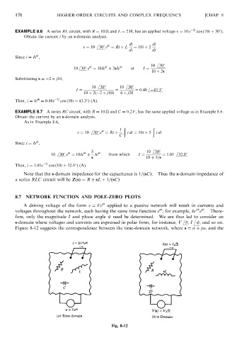
8.7 NETWORK FUNCTION AND POLE-ZERO PLOTS
st
A driving voltage of the form v ¼ Ve applied to a passive network will result in currents and
j st
st
voltages throughout the network, each having the same time function e ; for example, Ie e . There-
fore, only the magnitude I and phase angle need be determined. We are thus led to consider an
s-domain where voltages and currents are expressed in polar form, for instance, V , I , and so on.
Figure 8-12 suggests the correspondence between the time-domain network, where s ¼ þ j!, and the
Fig. 8-12