Page 176 - Schaum's Outline of Theory and Problems of Electric Circuits
P. 176

HIGHER-ORDER CIRCUITS AND COMPLEX FREQUENCY
               CHAP. 8]


                                                         Fig. 8-6                                    165

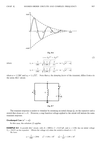
                                                    v ¼ A 1 e s 1 t  þ A 2 e s 2 t                   ð2Þ
                                                   s ffiffiffiffiffiffiffiffiffiffiffiffiffiffiffiffiffiffiffiffiffiffiffiffiffiffiffiffiffiffi
                                                            2           q ffiffiffiffiffiffiffiffiffiffiffiffiffiffiffiffi
                                              1        1       1
                                                                           2
               where                   s 1 ¼     þ               ¼   þ        ! 2 0
                                             2RC      2RC     LC
                                                   s ffiffiffiffiffiffiffiffiffiffiffiffiffiffiffiffiffiffiffiffiffiffiffiffiffiffiffiffiffiffi


                                              1        1   2   1        q ffiffiffiffiffiffiffiffiffiffiffiffiffiffiffiffi 2
                                                                           2
                                       s 2 ¼                     ¼            ! 0
                                             2RC      2RC     LC
                                          p ffiffiffiffiffiffiffi
               where   ¼ 1=2RC and ! 0 ¼ 1= LC.  Note that  , the damping factor of the transient, differs from   in
               the series RLC circuit.


                                                         Fig. 8-7

                   The transient response is easiest to visualize by assuming an initial charge Q 0 on the capacitor and a
               switch that closes at t ¼ 0.  However, a step function voltage applied to the circuit will initiate the same
               transient response.

                                 2    2
               Overdamped Case ð  >! 0 Þ
                   In this case, the solution (2) applies.

               EXAMPLE 8.4 A parallel RLC circuit, with R ¼ 1000 
, C ¼ 0:167 mF, and L ¼ 1:0 H, has an initial voltage
               V 0 ¼ 50:0 V on the capacitor. Obtain the voltage vðtÞ when the switch is closed at t ¼ 0.
                   We have
                                        1           2          6    2   1          6
                                     ¼    ¼ 2994     ¼ 8:96   10   ! 0 ¼  ¼ 5:99   10
                                      2RC                              LC
   171   172   173   174   175   176   177   178   179   180   181