Page 180 - Schaum's Outline of Theory and Problems of Electric Circuits
P. 180

169
                                 HIGHER-ORDER CIRCUITS AND COMPLEX FREQUENCY
               CHAP. 8]
               nonzero, the function is a damped cosine. Only negative values of   are considered. If   and ! are zero,
               the result is a constant.  And finally, with ! ¼ 0and   nonzero, the result is an exponential decay
                                                                                                      st
               function.  In Table 8-1, several functions are given with corresponding values of s for the expression Ae .
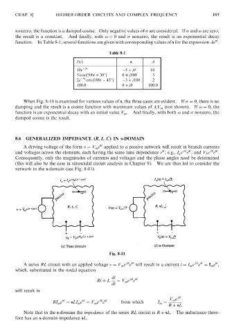
                                                        Table 8-1

                                          f ðtÞ                  s        A
                                          10e  5t              5 þ j      10
                                          5 cos ð500t þ 308Þ  0 þ j500     5
                                          2e  3t  cos ð100t   458Þ   3 þ j100  2
                                          100:0               0 þ j0     100.0


                   When Fig. 8-10 is examined for various values of s, the three cases are evident.  If   ¼ 0, there is no
               damping and the result is a cosine function with maximum values of  V m (not shown).  If ! ¼ 0, the
               function is an exponential decay with an initial value V m .  And finally, with both ! and   nonzero, the
               damped cosine is the result.


               8.6  GENERALIZED IMPEDANCE (R; L; C) IN s-DOMAIN
                                                    st
                   A driving voltage of the form v ¼ V m e applied to a passive network will result in branch currents
                                                                                                    j  st
                                                                                        j  st
                                                                               st
               and voltages across the elements, each having the same time dependence e ; e.g., I a e e , and V b e e .
               Consequently, only the magnitudes of currents and voltages and the phase angles need be determined
               (this will also be the case in sinusoidal circuit analysis in Chapter 9).  We are thus led to consider the
               network in the s-domain (see Fig. 8-11).


                                                        Fig. 8-11
                                                                j  st
                                                                                                      st
                                                                                             j  st
                   A series RL circuit with an applied voltage v ¼ V m e e will result in a current i ¼ I m e e ¼ I m e ,
               which, substituted in the nodal equation
                                                         di      j  st
                                                   Ri þ L  ¼ V m e e
                                                         dt
               will result in
                                                                                  V e j
                                                                                    m
                                            st
                                    st
                                                    j  st
                                RI m e ¼ sLI m e ¼ V m e e   from which      I m ¼
                                                                                  R þ sL
                   Note that in the s-domain the impedance of the series RL circuit is R þ sL.  The inductance there-
               fore has an s-domain impedance sL.
   175   176   177   178   179   180   181   182   183   184   185