
Page 185 - Schaum's Outline of Theory and Problems of Electric Circuits
P. 185
[CHAP. 8
HIGHER-ORDER CIRCUITS AND COMPLEX FREQUENCY
174
where the constants A 1 and A 2 are determined by applying the initial conditions to the complete response, i ¼ i n þ i f ,
where i f indicates the forced response.
EXAMPLE 8.11 The network of Fig. 8-16 is driven by current IðsÞ across terminals yy . 0 The network function is
HðsÞ¼ VðsÞ=IðsÞ¼ ZðsÞ. The three branches are in parallel so that
1 20s
HðsÞ¼ ZðsÞ¼ ¼
1 3 s ðs þ 2Þðs þ 6Þ
þ þ
2:5 5s 20
Again the poles are at 2 Np/s and 6 Np/s, which is the same result as that obtained in Example 8.10.
8.10 MAGNITUDE AND FREQUENCY SCALING
Magnitude Scaling
Let a network have input impedance function Z ðsÞ, and let K be a positive real number. Then, if
in
m
each resistance R in the network is replaced by K m R, each inductance L by K m L, and each capacitance C
by C=K m , the new input impedance function will be K m Z in ðsÞ. We say that the network has been
magnitude-scaled by a factor K m .
Frequency Scaling
If, instead of the above changes, we preserve each resistance R, replace each inductance L by L=K f
ðK f > 0Þ, and replace each capacitance C by C=K f , then the new input impedance function will be
Z in ðs=K f Þ. That is, the new network has the same impedance at complex frequency K f s as the old
had at s. We say that the network has been frequency-scaled by a factor K .
f
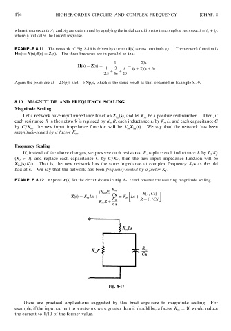
EXAMPLE 8.12 Express ZðsÞ for the circuit shown in Fig. 8-17 and observe the resulting magnitude scaling.
K m
ðK m RÞ Rð1=CsÞ
ZðsÞ¼ K m Ls þ Cs ¼ K m Ls þ
K m R þð1=CsÞ
K m R þ
Cs
Fig. 8-17
There are practical applications suggested by this brief exposure to magnitude scaling. For
example, if the input current to a network were greater than it should be, a factor K m ¼ 10 would reduce
the current to 1/10 of the former value.