Page 190 - Schaum's Outline of Theory and Problems of Electric Circuits
P. 190

HIGHER-ORDER CIRCUITS AND COMPLEX FREQUENCY
               CHAP. 8]
                                                          p ffiffiffi                                      179
               8.8   An amplitude and phase angle of 10 2 458 V has an associated complex frequency
                                     1
                     s ¼ 50 þ j 100 s . Find the voltage at t ¼ 10 ms.
                                                       p ffiffiffi
                                                vðtÞ¼ 10 2e  50t  cos ð100t þ 458Þ  ðVÞ
                     At t ¼ 10  2  s, 100t ¼ 1 rad ¼ 57:38, and so
                                                      p ffiffiffi
                                                 v ¼ 10 2e  0:5  cos 102:38 ¼ 1:83 V


               8.9   A passive network contains resistors, a 70-mH inductor, and a 25-mF capacitor.  Obtain the
                     respective s-domain impedances for a driving voltage (a) v ¼ 100 sin ð300t þ 458ÞðVÞ,
                                 100t
                     (b) v ¼ 100e   cos 300t ðVÞ.
                     (a) Resistance is independent of frequency.  At s ¼ j300 rad/s, the impedance of the inductor is
                                                                      3
                                                     sL ¼ð j300Þð70   10 Þ¼ j21
                         and that of the capacitor is
                                                            1
                                                              ¼ j133:3
                                                           sC
                                          1
                     (b)At s ¼ 100 þ j300 s ,
                                                                      3
                                                sL ¼ð 100 þ j300Þð70   10 Þ¼  7 þ j21
                                                1            1
                                                  ¼                    ¼ 40   j120
                                                                      6
                                               sC   ð 100 þ j300Þð25   10 Þ

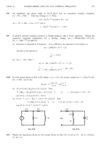
               8.10  For the circuit shown in Fig. 8-20, obtain v at t ¼ 0:1 s for source current ðaÞ i ¼ 10 cos 2t (A),
                                t
                     (b) i ¼ 10e cos 2t (A).
                                                            2ðs þ 2Þ   s þ 3
                                                  Z in ðsÞ¼ 2 þ   ¼ð4Þ
                                                             s þ 4     s þ 4
                     (a)At s ¼ j2 rad/s, Z in ð j2Þ¼ 3:22 7:138 
.  Then,

                          V ¼ IZ in ¼ð10 08Þð3:22 7:138Þ¼ 32:2 7:138 V  or   v ¼ 32:2 cos ð2t þ 7:138Þ  ðVÞ
                         and vð0:1Þ¼ 32:2 cos ð18:598Þ¼ 30:5V.
                                       1
                     (b)At s ¼ 1 þ j2s , Z in ð 1 þ j2Þ¼ 3:14 11:318 
.  Then
                                                                           t
                                    V ¼ IZ in ¼ 31:4 11:318 V  or  v ¼ 31:4e cos ð2t þ 11:318Þ  ðVÞ
                         and vð0:1Þ¼ 31:4e  0:1  cos 22:778 ¼ 26:2V.


                                     Fig. 8-20                                    Fig. 8-21

               8.11  Obtain the impedance Z in ðsÞ for the circuit shown in Fig. 8-21 at (a) s ¼ 0,  (b) s ¼ j4 rad/s,
                     (c) jsj¼ 1.
   185   186   187   188   189   190   191   192   193   194   195