
Page 206 - Science at the nanoscale
P. 206
10:16
RPS: PSP0007 - Science-at-Nanoscale
June 5, 2009
Nanotools and Nanofabrication
196
(b)
ccd camera
TV Monitor
s: Beam Splitter
L: Lens
M
M: Mirror
S
optical
He-Ne Laser
Microscope
M
(c)
L
L
Sample Stage
Carbon Nanotubes on Silicon
Carbon Nanotubes on Silicon
(mounted Sideway)
(mounted face-up)
(a)
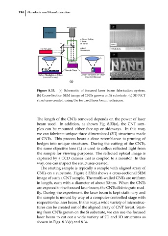
Figure 8.33.
(a) Schematic of focused laser beam fabrication system.
(b) Cross-Section SEM image of CNTs grown on Si substrate. (c) 3D NCT
structures created using the focused laser beam technique.
The length of the CNTs removed depends on the power of laser
beam used. In addition, as shown Fig. 8.33(a), the CNT sam-
ples can be mounted either face-up or sideways. In this way,
we can fabricate unique three-dimensional (3D) structures made
of CNTs. This process bears a close resemblance to pruning of
hedges into unique structures. During the cutting of the CNTs,
the same objective lens (L) is used to collect reflected light from
the sample for viewing purposes. The reflected optical image is
captured by a CCD camera that is coupled to a monitor. In this
way, one can inspect the structures created.
The starting sample is typically a sample with aligned array of ch08
CNTs on a substrate. Figure 8.33(b) shows a cross-sectional SEM
image of such a CNT sample. The multi-walled CNTs are uniform
in length, each with a diameter of about 30 nm. When the CNTs
are exposed to the focused laser beam, the CNTs disintegrate read-
ily. During the experiment, the laser beam is kept stationary and
the sample is moved by way of a computer-controlled stage with
respect to the laser beam. In this way, a wide variety of microstruc-
tures can be created out of the aligned array of CNT forest. Start-
ing from CNTs grown on the Si substrate, we can use the focused
laser beam to cut out a wide variety of 2D and 3D structures as
shown in Figs. 8.33(c) and 8.34.