
Page 202 - Science at the nanoscale
P. 202
10:16
RPS: PSP0007 - Science-at-Nanoscale
June 5, 2009
Nanotools and Nanofabrication
192
Looking at photon momentum
change in path a
Change in Momentum
Lens
Final Momentum
Initial
F
b
a
Momentum
F
F
a
b
By conservation of
momentum, momentum
a
change (i.e. force) on the
b
sphere
Fa
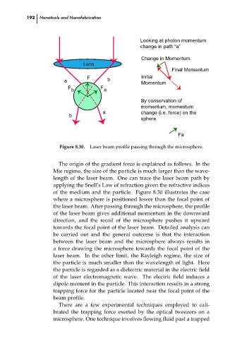
Figure 8.30.
Laser beam profile passing through the microsphere.
The origin of the gradient force is explained as follows. In the
Mie regime, the size of the particle is much larger than the wave-
length of the laser beam. One can trace the laser beam path by
applying the Snell’s Law of refraction given the refractive indices
of the medium and the particle. Figure 8.30 illustrates the case
where a microsphere is positioned lower than the focal point of
the laser beam. After passing through the microsphere, the profile
of the laser beam gives additional momentum in the downward
direction, and the recoil of the microsphere pushes it upward
towards the focal point of the laser beam. Detailed analysis can
be carried out and the general outcome is that the interaction
between the laser beam and the microsphere always results in ch08
a force drawing the microsphere towards the focal point of the
laser beam. In the other limit, the Rayleigh regime, the size of
the particle is much smaller than the wavelength of light. Here
the particle is regarded as a dielectric material in the electric field
of the laser electromagnetic wave. The electric field induces a
dipole moment in the particle. This interaction results in a strong
trapping force for the particle located near the focal point of the
beam profile.
There are a few experimental techniques employed to cali-
brated the trapping force exerted by the optical tweezers on a
microsphere. One technique involves flowing fluid past a trapped