
Page 197 - Science at the nanoscale
P. 197
RPS: PSP0007 - Science-at-Nanoscale
10:16
June 5, 2009
8.3. Scanning Probe Microscopy
Laser
Controller
Detector
electronics
electronics
Scanner
Photo-
detector
X, Y
Z
Piezo
Tip
Sample
(a)
(b)
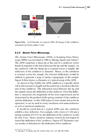
Figure 8.26.
(a) Schematic of a typical AFM. (b) Image of the cantilever
and probe tip (from author’s lab).
8.3.2
Atomic Force Microscopy
The Atomic Force Microscope (AFM), or Scanning Force Micro-
scope (SFM) was invented in 1986 by Binnig, Quate and Gerber.
The AFM comprises a sharp tip at the end of a cantilever which
bends in response to the force between the tip and the sample. As
the cantilever with the sharp tip is scanned across a sample, the
deflection of the cantilever is detected. Hence, as the cantilever
is scanned across the sample, the detected deflections would be
utilised to generate a map of surface topography of the sample.
Figure 8.26(a) shows a schematic of a typical setup of the AFM.
As shown in Fig. 8.26(b), the AFM cantilever is typically about
100 to 200 microns in length and the probe tip is located at the free
end of the cantilever. The interaction force between the tip and
the sample causes the deflection of the cantilever. Once the deflec-
tion is measured, the magnitude of the force experienced can be
determined by the product of the spring constant of the cantilever 7 187 ch08
and the deflection. As the AFM relies on inter-atomic forces for its
operation, it can be used to study insulators and semiconductors
as well as electrical conductors.
It should be noted that in a typical AFM scan, the cantilever
exhibits a tiny deflection. For example, with a force of 1 nN and a
spring constant of 0.5 N/m, the deflection of the cantilever would
be only 2 nm. Hence sensitive schemes need to be developed to
detect the deflection of the cantilever. Figure 8.27 illustrates vari-
ous modes of detection for the deflection of the cantilever.
7 G. Binnig, C. F. Quate and Ch. Gerber, Phys. Rev. Lett. 56, 930 (1986).