
Page 198 - Science at the nanoscale
P. 198
10:16
June 5, 2009
Nanotools and Nanofabrication
188
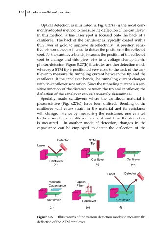
Optical detection as illustrated in Fig. 8.27(a) is the most com-
monly adopted method to measure the deflection of the cantilever.
In this method, a fine laser spot is focused onto the back of a
cantilever. The back of the cantilever is typically coated with a
thin layer of gold to improve its reflectivity. A position sensi-
tive photon-detector is used to detect the position of the reflected
spot. As the cantilever bends, it causes the position of the reflected
spot to change and this gives rise to a voltage change in the
photon-detector. Figure 8.27(b) illustrates another detection mode
whereby a STM tip is positioned very close to the back of the can-
tilever to measure the tunneling current between the tip and the
cantilever. If the cantilever bends, the tunneling current changes
with tip-cantilever separation. Since the tunneling current is a sen-
sitive function of the distance between the tip and cantilever, the
deflection of the cantilever can be accurately determined.
Specially made cantilevers where the cantilever material is
piezoresistive (Fig. 8.27(c)) have been utilised. Bending of the
cantilever will cause strain in the material and its resistance
will change. Hence by measuring the resistance, one can tell
by how much the cantilever has bent and thus the deflection
is measured.
In another mode of detection, changes in the
capacitance can be employed to detect the deflection of the
STM
Tip
Laser
Cantilever
Cantilever
(a) Detector RPS: PSP0007 - Science-at-Nanoscale Cantilever ch08
(c)
(b)
Laser Detector
Measure Optical
Capacitance Fiber
Cantilever Cantilever Cantilever
(d) (e) (f)
Figure 8.27. Illustrations of the various detection modes to measure the
deflection of the AFM cantilever.