Page 201 - Science at the nanoscale
P. 201

RPS: PSP0007 - Science-at-Nanoscale
                             10:16
                   June 5, 2009
                                                                            8.4. Optical Tweezers
                                        CCD Camera
                                                                             IIlumination
                                                                             Light Source
                                TV Monitor
                                                                              Sample Cell
                                                S: Beam Splitter
                                      M
                                                L: Lens
                                            S
                                                M: Mirror
                             He-Ne Laser
                                                Optical
                                                                             Objective Lens
                                                Microscope
                                                         IR Laser or
                                                                             Beam Splitter
                                       M
                                            L
                                                         He-Ne Laser
                                                                             Camera
                                                       L
                                           Sample
                                                                              TV
                                     Sample Stage
                                                                    Computer
                                                                    Image Processing
                                               Aqueous Suspension
                                               of Colloidal Microspheres
                                                                              VCR
                               Using Upright Optical Microscope
                                                             Using Inverted Optical Microscope
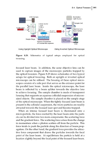
                             Figure 8.29.
                                         Schematics of typical setups employed for optical
                             tweezing.
                             focused laser beam. In addition, the same objective lens can be
                             used to capture images of the microscopic particles trapped by
                             the optical tweezers. Figure 8.29 shows schematics of two typical
                             setups for optical tweezing. Both an upright or inverted optical
                             microscope can be utilised. The housing of these optical micro-
                             scopes consists of a side port that serves as the entrance point for
                             the parallel laser beam. Inside the optical microscope, the laser
                             beam is reflected by a beam splitter towards the objective lens
                             to achieve focusing. The sample chamber is made of transparent
                             housing that supports an aqueous colloidal suspension of micron-
                             sized objects. The sample chamber is placed on the sample stage
                             of the optical microscope. When the tightly focused laser beam is
                             present in the colloidal suspension, the micro-particles are readily  191  ch08
                             attracted towards the focused laser spot and become trapped.
                               When an intense focused laser beam is illuminated onto a
                             micro-particle, the force exerted by the laser beam onto the parti-
                             cle can be divided into two main components: the scattering force
                             and the gradient force. The scattering force arises from the change
                             in momentum when a photon scatters off from the particle. This
                             force tends to push the particle along the direction of beam prop-
                             agation. On the other hand, the gradient force provides the attrac-
                             tive force component that draws the particles towards the focal
                             point of the laser beam. At equilibrium the particle is held at a
                             location slightly beyond the focal point of the focused laser beam.
   196   197   198   199   200   201   202   203   204   205   206