
Page 132 - Semiconductor Manufacturing Handbook
P. 132
Geng(SMH)_CH10.qxd 04/04/2005 19:46 Page 10.5
ION IMPLANTATION AND RAPID THERMAL PROCESSING
ION IMPLANTATION AND RAPID THERMAL PROCESSING 10.5
might help to neutralize that space charge are excluded from any region with finite electrostatic
fields.
The analyzer magnet in high-current tools typically bends the beam through approximately 90°
with a radius of approximately 300 mm. The distance from the ion source to the entrance of the ana-
lyzer magnet is typically no more than 200 to 300 mm, with a similar distance from the exit of the
analyzer magnet to the resolving aperture. The distance from the resolving aperture to the wafer is
in the range of 400 to 700 mm, producing a total beamline length in the range of 1.5 to 2 m.
Emerging from the ion source and extraction optics, the beam is approximately 50 mm tall and
converging slightly (in the nondispersive plane), and approximately 5 mm wide and diverging (in the
dispersive plane). In the dispersive plane, the beam is focused by the analyzer magnet to a waist at
the resolving aperture. The beam size passing through the resolving aperture is approximately 5 to
25 mm, depending largely on the energy. The beam arrives at the wafer with a dispersive plant size
in the range of 30 to 100 mm. In the nondispersive plane, there is typically much less focusing
applied to the beam and the size of the beam is similar (approximately 50 mm) from the source to
the wafer.
Most ion implanters with the simple fixed-spot beamlines described previously also make use of
multi-wafer process chamber geometries (see the following section) to improve overall tool produc-
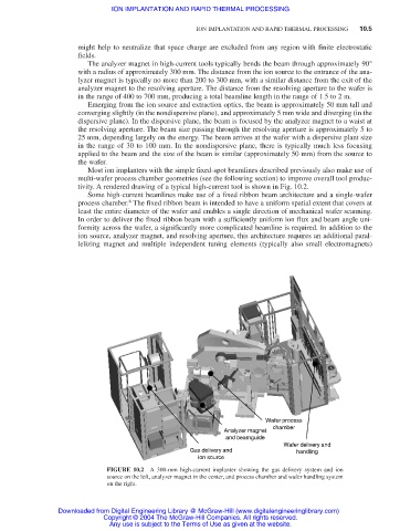
tivity. A rendered drawing of a typical high-current tool is shown in Fig. 10.2.
Some high-current beamlines make use of a fixed ribbon beam architecture and a single-wafer
8
process chamber. The fixed ribbon beam is intended to have a uniform spatial extent that covers at
least the entire diameter of the wafer and enables a single direction of mechanical wafer scanning.
In order to deliver the fixed ribbon beam with a sufficiently uniform ion flux and beam angle uni-
formity across the wafer, a significantly more complicated beamline is required. In addition to the
ion source, analyzer magnet, and resolving aperture, this architecture requires an additional paral-
lelizing magnet and multiple independent tuning elements (typically also small electromagnets)
Wafer process
chamber
Analyzer magnet
and beamguide
Wafer delivery and
Gas delivery and handling
ion source
FIGURE 10.2 A 300-mm high-current implanter showing the gas delivery system and ion
source on the left, analyzer magnet in the center, and process chamber and wafer handling system
on the right.
Downloaded from Digital Engineering Library @ McGraw-Hill (www.digitalengineeringlibrary.com)
Copyright © 2004 The McGraw-Hill Companies. All rights reserved.
Any use is subject to the Terms of Use as given at the website.