
Page 134 - Semiconductor Manufacturing Handbook
P. 134
Geng(SMH)_CH10.qxd 04/04/2005 19:46 Page 10.7
ION IMPLANTATION AND RAPID THERMAL PROCESSING
ION IMPLANTATION AND RAPID THERMAL PROCESSING 10.7
through to the wafer. This magnet is typically tuned to a known deflecting field, based on some cal-
ibration with dc drift beams, to pass only those ions in the beam packet that are of the desired
momentum (typically synonymous with saying that those ions are at the desired energy, since the
mass is known).
Emerging from the ion source and extraction optics, the dc beam is typically smaller than in high-
current tools, both in the dispersive and nondispersive planes, by approximately a factor of two. The
typical beam diameter passing through the linac and exiting the FEM is no larger than about 20 mm
and this beam arrives at the wafer typically no larger than approximately 30 mm in diameter. The
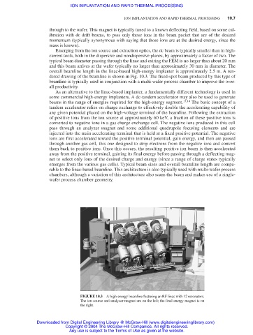
overall beamline length in the linac-based high-energy implanter is approximately 2.5 m. A ren-
dered drawing of the beamline is shown in Fig. 10.3. The fixed-spot beam produced by this type of
beamline is typically used in conjunction with a multi-wafer process chamber to improve the over-
all productivity.
As an alternative to the linac-based implanter, a fundamentally different technology is used in
some commercial high-energy implanters. A dc-tandem accelerator may also be used to generate
beams in the range of energies required for the high-energy segment. 13,14 The basic concept of a
tandem accelerator relies on charge exchange to effectively double the accelerating capability of
any given potential placed on the high-voltage terminal of the beamline. Following the extraction
of positive ions from the ion source at approximately 60 keV, a fraction of these positive ions is
converted to negative ions in a gas charge exchange cell. The negative ions produced in this cell
pass through an analyzer magnet and some additional quadrupole focusing elements and are
injected into the main accelerating terminal that is held at a fixed positive potential. The negative
ions are first accelerated toward the positive terminal potential, gain energy, and then are passed
through another gas cell, this one designed to strip electrons from the negative ions and convert
them back to positive ions. Once this occurs, the resulting positive ion beam is then accelerated
away from the positive terminal, gaining its final energy before passing through a deflecting mag-
net to select only ions of the desired charge and energy (since a range of charge states typically
emerges from the various gas cells). Typical beam sizes and overall beamline length are compa-
rable to the linac-based beamline. This architecture is also typically used with multi-wafer process
chambers, although a variation of this architecture also scans the beam and makes use of a single-
wafer process chamber geometry.
FIGURE 10.3 A high-energy beamline featuring an RF linac with 12 resonators.
The ion source and analyzer magnet are on the left; the final energy magnet is on
the right.
Downloaded from Digital Engineering Library @ McGraw-Hill (www.digitalengineeringlibrary.com)
Copyright © 2004 The McGraw-Hill Companies. All rights reserved.
Any use is subject to the Terms of Use as given at the website.